well thanks for pointing this out and by finishing the post i just remembered how i started ( and when ) in this job .....
---at the age of 6-7 i was already reading Greek versions of elektor and a couple of other generic Greek magazines
--- at the age of 9 had my first basement lab with regulated power supply all shorts of cables , soldering equipment , multimeter , and performed my first repairs while spending all my allowance in parts regulators capacitors and parts
---at the age of 13 i quite day school move on to night school to start working for a company that supply electrics sound and lighting for clubs and theaters ...then of course my payment was transformed to by far sophisticated parts and tolls ...
---At the age of 16 i was experienced enough to built small cafes and small bar clubs from scratch .... that will include everything ( low tech at the time ) installation of sound systems and lighting dimmers wiring light effects and so on ...
--- also at the same time i produced a few amps kit based but kind of upgraded as about the quality of parts and size of capacitors ...some of them still work till today and surprise to listen that some of them still work after awesome 30 years of operation....
you ''ll be surprised what kids can do some time
Hi Sakis.
Very well said. Childs minds are so receptive of imformation and knolage and should be encouraged with a passion. However as children we enjoy taking risks and this is the difficult part as we all dont want them to be injured or killed. I would like to get involved in producing safe projects for minors. If anyone else is intrested let me know and we can discuss it further. Pass the knolage to the youger generations as there is no point in taking it to our graves.
Seasons greetings to all.
Best Wishes
Ian
Think of the children!
Seriously though, as long as he is careful with wiring the primary side of the transformer, makes sure everything is insulated etc, and keeps his hands away when the circuit is powered he will be fine. I built my first mains powered PSU at 14 and survived")
Seriously though, as long as he is careful with wiring the primary side of the transformer, makes sure everything is insulated etc, and keeps his hands away when the circuit is powered he will be fine. I built my first mains powered PSU at 14 and survived
There are some interesting points regarding Rod's 60w amp and his audio page offer's a door way to understanding audio electronics, how ever, he doe's state some project's are not for the total leaner and give plenty of warning's about the high voltages within circuits..
good luck to the young 15 yr with his build and we many see his finished work on here.
good luck to the young 15 yr with his build and we many see his finished work on here.
Francec,
U have not seen what respect the mains voltage gets here. Most people here do not use a plug. They will just push the wires into the socket.
Gajanan Phadte
Yes sir! I totally agree!!
well ...it seems that from the things i told you you have done almost nothing.....
your pcb will work ( produce sound) as is as i said if you are aiming to really high quality sound this pcb cannot go there
jay cee has given you also some useful advice....
--- you use a jumper to supply Q1-2 which is actually ok but proximity between traces is not right .... you can actually do that better
--- Making such a big circle around + rail around the power transistor is not OK ...better with a jumper
--- you forgot to relocate C6
--- you was advised to make Q1-2 go face to face .... it works better for mechanical reasons not one behind the other
--- you was advised to move Q9 close to the driver
--- Finally the all pcb can be rearranged to be more more clean and reorganized see how others did and see what you like to keep
Sir, i've read your reply while i was in a hurry and i was desperate to post the layout..! So i have ruined it..Please give me a couple of days so that i can revert back to you. Im currently having my exams now. So i'm in a hassle nowadays..
But i'm sure that i'll get back to you!
Get hold of Randy Slone's book "High Power Audio Amplifier Construction Manual" and look at the figure 11-1 project. It is based upon the original proven circuit from the Hitachi databook. There is a PCB layout as well.
Thanks, i'll surely go for it.
From what I can make out, paranoid06 should give up on the original idea and go with a chip amp, probably LM1875 because of lower voltage requirements. This project is too ambitious for someone with clearly limited skills and knowledge and is, potentially, lethal. As it will involve mains wiring, I am unesy about anyway.
paranoid, do your parents understand the dangers?
I am fiddling with electronics since i was around 5 years. At the age of 6, i tried to run a 12V dc motor on 230VAC! And that was all... BOOM!
The motor got burnt and my MCB got tripped (Permanently!) Had to replace it!
I don't know, but that motor was quite capable of killing a 15A MCB!! That day, my mom n dad whacked me like anything...!
Then some years later...(Still small) I tried to measure voltage across The live and the earth in the wall socket...Burnt my first multimeter
I remember those days of my first accidents and since then i'm very careful with High Voltages..!
So Don't Worry
sakis, the kid is 15!
His/her parents have a right and obligation to know what their child is up to and the dangers involved. We have an obligation to ensure a young kid is not harmed through our advice. I tempered my comments above by saying I was uneasy with any project that involved mains voltages. In Oz, it is 230V and it kills. I just checked and India is 230V as well.
Purely from self-interest, can you imagine the problems for this forum and us as members if something tragic happened and the kid was acting on OUR advice and was killed. However, that is far less important than ensuring, for moral and ethical reasons, the safety of the child.
Pleas of "give the kid a chance" border on irresponsible and I will treat them with the contempt it deserves. Does the kid properly understand safety issues and the potential of mains voltages to harm and kill? If you can guarantee he/she does, let me know with an ironclad assurance. Otherwise, give advice that is less potentially harmful.
My advice for the kid is to start with a 12V project or with a pre-built power supply that complies with electrical safety regulations.
Frank
My parents are aware of what i am up to and i don't think i'll die so early!
And i have built chipamps with LM3886. And i dont like it!
Even though.....MISTAKES CAN HAPPEN ANYTIME! Lets hope for THE BEST!
point taken and basically i totally agree with you but this could happen to any of us
even a grown up can make a mistake.
Let us wait for the OP to tell us his opinion see if he has an safety background and/or if we can also help there
kind regards
sakis
Once again!! I'm pretty alert while using high voltages
Think of the children!
Seriously though, as long as he is careful with wiring the primary side of the transformer, makes sure everything is insulated etc, and keeps his hands away when the circuit is powered he will be fine. I built my first mains powered PSU at 14 and survived
Survived....
LOL There are some interesting points regarding Rod's 60w amp and his audio page offer's a door way to understanding audio electronics, how ever, he doe's state some project's are not for the total leaner and give plenty of warning's about the high voltages within circuits..
good luck to the young 15 yr with his build and we many see his finished work on here.
I visit his page everyday....! Very few people are there who dare to distribute their whole lifetime's hardwork to the whole damn world...!
I respect him from the bottom of my heart...
Regards
Hi paranoid .
At the age of 15 i do not concider you to be a child. i was talking in genral as there are on occasion minors of a younger age than yourself ie children that come to this forum and the responses they recive range from dont do it its dangerous to dont worry about it some of the members that advise change there tune depending on what flag is being flown and that is a sad state of affairs. I wish you every succses in your hobby and as long as saftey for yourself and others that may come into contact with the equipment you build is observed then all is good in my book..
There is is religon poltics and diy audio and forums.
Regards Ian
This inspires exactly zero confidence in me.Hi paranoid .
At the age of 15 i do not concider you to be a child. i was talking in genral as there are on occasion minors of a younger age than yourself ie children that come to this forum and the responses they recive range from dont do it its dangerous to dont worry about it some of the members that advise change there tune depending on what flag is being flown and that is a sad state of affairs. I wish you every succses in your hobby and as long as saftey for yourself and others that may come into contact with the equipment you build is observed then all is good in my book..
There is is religon poltics and diy audio and forums.
Regards Ian
Also giving zero confidence are those people who extol their professed considerable achievements (prodigies, anyone?) in their youth through rose coloured glasses.
This even less, if that is possible. (It was rhetorical so don't chide me.) A six year old playing around with 230V is not my idea of responsible parenting either.At the age of 6, i tried to run a 12V dc motor on 230VAC! And that was all... BOOM!
Paranoid, do listen to the experienced posters here!
I'll add my 2c worth as well. Make sure ANY exposed mains wiring is insulated (for example using heat shrink tubing). Connections to switches, fuse terminals etc. It's all to easy to brush against a live mains wire when you are poking around inside an amp if they aren't insulated!
Also make sure the mains cable is correctly anchored so it cannot pull out, and that Earth connections are properly attached and also securely anchored. Make sure you heed the warnings on Rod's site!
Tony.
This inspires exactly zero confidence in me.
Also giving zero confidence are those people who extol their professed considerable achievements (prodigies, anyone?) in their youth through rose coloured glasses.
This even less, if that is possible. (It was rhetorical so don't chide me.) A six year old playing around with 230V is not my idea of responsible parenting either.
DO NOT SPEAK ABOUT MY PARENTS....you may be a senior member but i respect my parents more than you..they are not even at fault...i used to do all this whenever they were not at home...so stop assuming 'irresponsible parenting' without knowing about the circumstances.....
...now things are getting out of hand ..... i dont think that any one wanted to insult your parents in any way ...obviously most of your friends here have safety concerns and that's about it ...
work on your amplifier forum is a nice place with nice people suck the knowledge out of them they will give it happily
kind regards
sakis
work on your amplifier forum is a nice place with nice people suck the knowledge out of them they will give it happily
kind regards
sakis
here is a picture of a layout i made a year ago ...get some ideas from there if you like http://www.diyaudio.com/forums/solid-state/164756-p3a-comparsion-table-long-7.html#post2234094
Paranoid,
Where is your new pcb artwork(pictures).
Gajanan Phadte
Sir, ill be working on the new layout....redesigning it...!
here is a picture of a layout i made a year ago ...get some ideas from there if you like http://www.diyaudio.com/forums/solid-state/164756-p3a-comparsion-table-long-7.html#post2234094
I read the whole thread!
And I am thinking of starting the design all over...!
I'll get back to you within 3-4 days with the new layout..!
I'll keep all the points in mind that you and fellow members have suggested me regarding this layout
Thanks a lot sir...
You have helped a lot.
By the time I am able to make the layout i have some further difficulties
I am using P3A for my Hi-Fi System
It will be a 2 Way system with an Active Crossover.
I am using the P3A for the lower frequency. What should i use for the High Frequency?
Willl the LM1875 Amp (20W) fulfill my needs??
Regards
I am using P3A for my Hi-Fi System
It will be a 2 Way system with an Active Crossover.
I am using the P3A for the lower frequency. What should i use for the High Frequency?
Willl the LM1875 Amp (20W) fulfill my needs??
Regards
it will but discrete amplifiers are more playful and here is always room for improvment or changes if something goes wrong ...
i could go for 4 P3a boards
I've uploaded the new layout. Made it taking reference from your layout.
Regards
If you're building two, you might as well do four.
I have a SONY 4" Tweeters!
Is P3A too much for it?? Or its fine??
Regards
Attachments
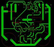
I did not check the circuit for accuracy, but here are a few obvious things:
- C7 and C3 cannot share the same thin track down to ground. C3 is signal and should connect directly on the incoming signal ground point.
- C4 and C6 should be rotated to have very short tracks to Q4/Q6.
- There are no power connection points and fuses?
- There are two unused pads around Q9?
- A film capacitor is much more preferred for C1. A square box MKS/MKT type with 5mm lead spacing will fit in the same space.
- C7 is usually a 250V unit, it will be physically bigger than shown.
- Try to move R15/C7 a little bit away from the sensitive signal devices on the board. At least switch position with R5/R4/C3.
- R8 could be next to R4 with the ground track running straight down, removing the convoluted track between Q3 and R8.
- I would move the big power capacitors closer to Q7 and Q8 and run the main ground through the middle of the board. This would get the signal section outside of the loop formed by the power rails, R13/R14 and the main ground track. This may add 2 or 3 jumpers.
It is progressing nicely though!
Last edited:
I did not check the circuit for accuracy, but here are a few obvious things:
- C7 and C3 cannot share the same thin track down to ground. C3 is signal and should connect directly on the incoming signal ground point.
- C4 and C6 should be rotated to have very short tracks to Q4/Q6.
- There are no power connection points and fuses?
- There are two unused pads around Q9?
- A film capacitor is much more preferred for C1. A square box MKS/MKT type with 5mm lead spacing will fit in the same space.
- C7 is usually a 250V unit, it will be physically bigger than shown.
- Try to move R15/C7 a little bit away from the sensitive signal devices on the board. At least switch position with R5/R4/C3.
- R8 could be next to R4 with the ground track running straight down, removing the convoluted track between Q3 and R8.
- I would move the big power capacitors closer to Q7 and Q8 and run the main ground through the middle of the board. This would get the signal section outside of the loop formed by the power rails, R13/R14 and the main ground track. This may add 2 or 3 jumpers.
It is progressing nicely though!
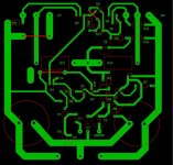
Bringing the big capacitors in the middle will be very fussy!! Don't you think so??!
Don't worry, i remember that I have to apply power to the amp!
The fuses will be on another board or maybe in the circular fuse holders, user replaceable ones.
The two empty pads around Q9 was a jumper.Forgot to show it!
I have attached the edited layout.
Thanks and Regards
Attachments
- Home
- Amplifiers
- Solid State
- Rod Elliot P3A Layout - Critics