The board # is PC-4309-H
I need the following values to these listed parts, they are blown to bits beyond recognition:
R37
Q112
Q113
R173
R50
R33
R45
R153, R198, R154, R183, R104, R186
Q10
Q107
R156
R149
R146
This what i physically see blown/cooked and cannot make out.
who knows what else is bad. probably all the outputs too.
Got everything done, but now i am having a serious issue.
The 9540 output side is working normally. the IRF540 side is blowing the fets. there is +25V between G and S
Further troubleshooting reveils that the bases of Q12/Q13 is only -13v. While Q10/11 is +37v
Tracing even further back, Q116 isnt turning on, it appears to be a current source? not sure. But it isnt turning on. Therefore, i am not getting the -37v where there is only -13v
any ideas? i checked all remaining resistors and transistors, comming up empty.
rail voltage is +/-40v
I did more troublehsooting, the BIAS transistor Q109 isnt turning on, so about 2 to 4 seconds after powerup, the entire bias circuit pulls negative. -13v forcing the IRF540s past thier gate specs.
The gates start off about 0v. then when the bias circuit snaps negative, the vGS shoots to +25v which blows the IRF540s.
DC doesnt become present until 540s short at poweron.
I have the outputs removed from circuit. the IRF9540 section of the amplifier is working perfect.
I cannot find Q110 anywhere, so theres a chance this schematic may not be correct.
I removed Q111 to stop the BIAS circuit from getting its negative source, it allows the IRF540s to run without getting blown. But no audio from that half of the amp, still no negative half of the wave on the output.
Sooooo, i noticed it has 2 sets of differential drivers. My guess is one of them is toast. the transistors are statically checking ok, same with the resistors, but i guess that dont mean it isnt breaking down under load.
Sooooo, i noticed it has 2 sets of differential drivers. My guess is one of them is toast. the transistors are statically checking ok, same with the resistors, but i guess that dont mean it isnt breaking down under load.
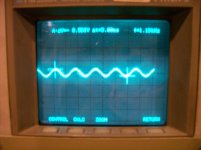
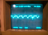
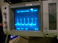
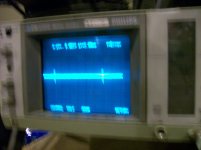
I am at a loss. Here is the scope shots, I am using a 1.25Khz Sine Wave as an input signal.
These are AC measurements. DC is too far off the scale over signal. So i cant really measure.
The input signal is shown, the rest are taken off of the collectors of Q102, Q103, Q104, Q105 which is the differential setup.
I replaced ALL transistors. problem still exists.
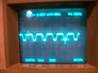
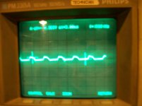
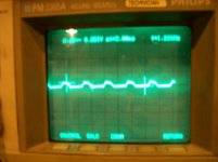
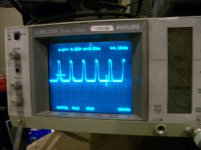
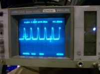
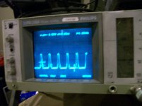
These are AC measurements. DC is too far off the scale over signal. So i cant really measure.
The input signal is shown, the rest are taken off of the collectors of Q102, Q103, Q104, Q105 which is the differential setup.
I replaced ALL transistors. problem still exists.
Attachments
On this type of circuit, the most common failures (after the outputs, source resistors and gate resistors) are the 20 ohm resistors and the driver transistors (connected to the 20 ohm resistors).
Are you sure that there are no solder bridges or similar problems?
I know, i replaced them once. on both sides. including the 20 ohm resistors.
But if I use 220ohm resistors, the amplifier is happy. If i stick the 20 ohm resistors back in, it blows the drivers out again.
- Status
- This old topic is closed. If you want to reopen this topic, contact a moderator using the "Report Post" button.
- Home
- General Interest
- Car Audio
- Rockford Punch 301m