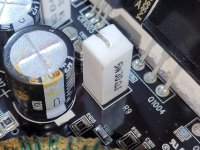
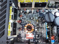
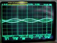
Hello fellow techs i need help so I recently got a punch P1000-1bd on a trade so it would power on but had strange waveforms almost like multiple waves amplitudes picked up at same time. After looking closely I found R9 30ohm 2/3 watt resistor had broke a lead so I replaced it with a 30ohm 5 watt resistor I had on hand and now the amp powers on and power supply waveforms look great.
When measuring between rectifiers I get 53.3vdc @2.18Amps on the lab P.S. there's no DC offset and with signals injected there's no audio. So after probing the output section with the scope I found that half of the output section appears to be wonky from what I'm used to seeing.
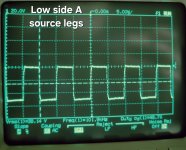
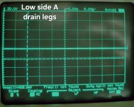
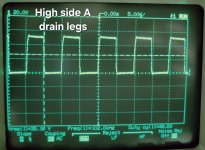
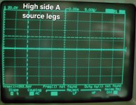
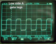
So highside A & lowside A looks how I would assume it should however
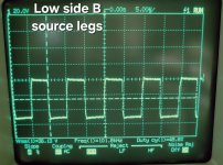
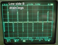
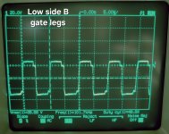
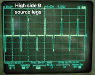
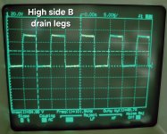
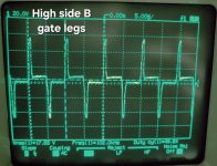
highside B & lowside B looks off. I believe im getting voltage were there shouldn't be and it looks like it's picking up 2 frequencies on the same waveform.
I added pics of the resistor R9 that broke and of the waveforms from the output section labeled as above.
Any help would be greatly appreciated this amp circuit is a new one for me and I can't find a service manual thanks for reading.
When measuring between rectifiers I get 53.3vdc @2.18Amps on the lab P.S. there's no DC offset and with signals injected there's no audio. So after probing the output section with the scope I found that half of the output section appears to be wonky from what I'm used to seeing.
So highside A & lowside A looks how I would assume it should however
highside B & lowside B looks off. I believe im getting voltage were there shouldn't be and it looks like it's picking up 2 frequencies on the same waveform.
I added pics of the resistor R9 that broke and of the waveforms from the output section labeled as above.
Any help would be greatly appreciated this amp circuit is a new one for me and I can't find a service manual thanks for reading.
Attachments
-
 20240318_204525.jpg454.1 KB · Views: 31
 -
 20240318_204304.jpg384 KB · Views: 29
 -
 20240318_204259.jpg450.4 KB · Views: 23
 -
 20240318_204251.jpg452.9 KB · Views: 23
 -
 20240318_204241.jpg435.2 KB · Views: 24
 -
 20240318_204231.jpg400.6 KB · Views: 25
 -
 20240318_204217.jpg375 KB · Views: 25
 -
 20240318_204207.jpg373 KB · Views: 23
 -
 20240318_204201.jpg361.5 KB · Views: 28
 -
 20240318_224251.jpg716.4 KB · Views: 29
 -
 20240318_204103.jpg390.9 KB · Views: 34
 -
 20240318_204122.jpg387.3 KB · Views: 26
 -
 20240318_204139.jpg368.3 KB · Views: 26
 -
 20240318_204153.jpg419.4 KB · Views: 30
Last edited:
When measuring between rectifiers I get 53.3vdc @2.18Amps on the lab P.S.
^^^ Measuring between the center legs of the rectifiers and you read 53v?
And as a completely separate issue, there is a 2 amp draw from your 12v power supply?
What is the DCV across Ground and B+? Across ground and remote?
Are all parts in the amp?
^^^ Measuring between the center legs of the rectifiers and you read 53v?
And as a completely separate issue, there is a 2 amp draw from your 12v power supply?
What is the DCV across Ground and B+? Across ground and remote?
Are all parts in the amp?
Sorry for the confusion Perry when measuring between rectifiers middle legs it is 53.4vdc.
The 2.18amps is being drawn from my 12v supply when amp is powered on.
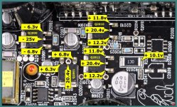
Across the B+ and ground is 11.8vdc
Across remote and ground is 11.6vdc
All parts are in amp and is fully assembled except top cover is off and clear plastic led light stand offs.
The 2.18amps is being drawn from my 12v supply when amp is powered on.
Across the B+ and ground is 11.8vdc
Across remote and ground is 11.6vdc
All parts are in amp and is fully assembled except top cover is off and clear plastic led light stand offs.
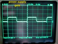
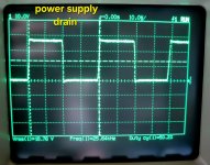
I just wanted to make sure that 13.5vdc was the voltage you wanted. So according to the scope I have 18.78vdc @ 50.2%duty cycle on the power supply fets drains.
On the gates of the power supply fets there is 7.691vdc @45.7%duty cycle.
Pics added.
On the gates of the power supply fets there is 7.691vdc @45.7%duty cycle.
Pics added.
Attachments
All the voltages are basically spot on.
Ok so I realized I made a mistake when I hooked the speaker up to the amp earlier I had the speaker wires in both positive terminals smh.
So when I went to connect the subwoofer to test output waveform I realized I had it wired wrong so I put them in correctly and the amp is playing audio and sounds clean no distortion.
And the wonky waveform from post #1 on highsideB gate and source legs and lowside B drain is modulating with the audio but still nothing on highside And lowside A that's what through me of on this one why one side of the output section different?
Attachments
So it would appear that after replacing the R9 30ohm resistor it was working but I had the speaker wire locations mixed up and that's why I had no output on scope or speaker. However the waveforms on highside B and lowside B since they were different from highside A & lowside A
I assumed there was an issue. I'm so sorry Perry if I wasted your time at all.
So would it appear it is working or should I be worried about the 2.18amps of draw.
I assumed there was an issue. I'm so sorry Perry if I wasted your time at all.
So would it appear it is working or should I be worried about the 2.18amps of draw.
I don't think the current draw is excessive.
In notes for a T1500, I have 1.3 amps draw before the output stage engages and 3.2 amps after the output begins to oscillate.
Those waveforms were strange but if the amp drives the lowest rated load symmetrically rail to rail, it could have been the way the waveforms were captured.
For future reference, if there is a drive issue with BD amplifiers, it's typically easiest to troubleshoot to do so without rail voltage. A,, you need to do is to close the feedback loop at the feedback/servo op-amp and you will get a 50% duty cycle. That was going to be my next step.
As a side note, that 30 ohm resistor is a 5w.
- Home
- General Interest
- Car Audio
- Rockford Fosgate P1000-1BD (HELP)