Hello,
you were right eveything works fine, both channels, with low and high gain. It's now burning in.
Now i need another jack socket because the one I have doesn't fit in my case.
Here a picture while waiting for those ''adhesive cable tie base''")
you were right eveything works fine, both channels, with low and high gain. It's now burning in.
Now i need another jack socket because the one I have doesn't fit in my case.
Here a picture while waiting for those ''adhesive cable tie base''
An externally hosted image should be here but it was not working when we last tested it.
hello,
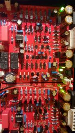
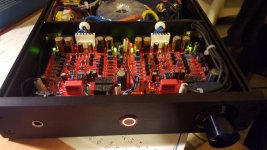
just wanna share with you my sapphire headphone amplifier build. I redesigned the pcbs because i wanted to add a relay delay circuit for the loop output (i have the amp connected between preamp and active cross so when i power it on the output must be muted) and i wanted to have the rectifiers on the board too. Those pcbs were manufactured by pcbway.com as always. The cost for these boards (5pcs) double sided and size 100x100mm was only 13$ plus shipping from them. The boards very good quality can be seen on the photos.
I have no audible noise at the output. I use a smaller transformer which is always on only for the startup circuit. By using this circuit i don't have 220v on/off switch at the front (but only 5v button) so there is no 220v wires near the amp pcbs. The 220v input passes through a line filter and the chassis is grounded. The amplifier ground is connected to the chassis ground ( through a X2 0.1u capacitor parallel to 100ohm resistor) at the same point as the power line ground. The left and right channel ground are connected only at one point (at the headphone plug) The gain is 26db (for hd650 headphones).
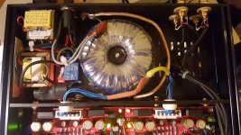
As you can see i use only one toroid transformer 50va with 5outputs of 12V (one is only for the relay circuit). The opamps are the opa637 which i bought several years ago and never used them.
i have listened this amplifier only for a few hours. I must say that i like how it sounds.
just wanna share with you my sapphire headphone amplifier build. I redesigned the pcbs because i wanted to add a relay delay circuit for the loop output (i have the amp connected between preamp and active cross so when i power it on the output must be muted) and i wanted to have the rectifiers on the board too. Those pcbs were manufactured by pcbway.com as always. The cost for these boards (5pcs) double sided and size 100x100mm was only 13$ plus shipping from them. The boards very good quality can be seen on the photos.
I have no audible noise at the output. I use a smaller transformer which is always on only for the startup circuit. By using this circuit i don't have 220v on/off switch at the front (but only 5v button) so there is no 220v wires near the amp pcbs. The 220v input passes through a line filter and the chassis is grounded. The amplifier ground is connected to the chassis ground ( through a X2 0.1u capacitor parallel to 100ohm resistor) at the same point as the power line ground. The left and right channel ground are connected only at one point (at the headphone plug) The gain is 26db (for hd650 headphones).
As you can see i use only one toroid transformer 50va with 5outputs of 12V (one is only for the relay circuit). The opamps are the opa637 which i bought several years ago and never used them.
i have listened this amplifier only for a few hours. I must say that i like how it sounds.
Attachments
Last edited:
Hello,
you were right eveything works fine, both channels, with low and high gain. It's now burning in.
Now i need another jack socket because the one I have doesn't fit in my case.
Here a picture while waiting for those ''adhesive cable tie base''
An externally hosted image should be here but it was not working when we last tested it.
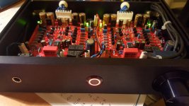
a very well build amplifier except the earth point. On the photo i see (maybe i cannot see it right) that you are using the transformer screw as earth point. That is not so good because you are creating one secondary shorted loop.(if the chassis is grounded at another point also)
You are right, but it's the only ground / chassis connection. For my last build I did a dedicated hole, but for this I thought why not use one already done ? You think I should change that ?
You have yourself a very nice build too. I also tried to keep AC as far as possible from the signal path, except for the 2nd transformer, but I had no choice. Well i don't hear any interference so I guess it's good enough.
You think I should change that ?You have yourself a very nice build too. I also tried to keep AC as far as possible from the signal path, except for the 2nd transformer, but I had no choice. Well i don't hear any interference so I guess it's good enough.
hello,
just wanna share with you my sapphire headphone amplifier build. I redesigned the pcbs because i wanted to add a relay delay circuit for the loop output (i have the amp connected between preamp and active cross so when i power it on the output must be muted) and i wanted to have the rectifiers on the board too. Those pcbs were manufactured by pcbway.com as always. The cost for these boards (5pcs) double sided and size 100x100mm was only 13$ plus shipping from them. The boards very good quality can be seen on the photos.
That looks amazing. Very nice work. I notice you have a metal chassis divider between the transformers and the amp boards. In my own experience this is desirable for lowest noise... though magnetically shielding the transformers worked out ok for me in the end.
$13 with no tooling costs? That's unbelievable cheap, I'll have to look into them. pcbcart is good, but the ~$50 tooling charge means you take a big hit on small quantities.
a very well build amplifier except the earth point. On the photo i see (maybe i cannot see it right) that you are using the transformer screw as earth point. That is not so good because you are creating one secondary shorted loop.(if the chassis is grounded at another point also)
Indeed, that looks really dangerous.
The two black wires from the board GND can bolt to the chassis directly at a single point, somewhere up front near the boards.
The earth connection from the AC socket should bolt to the chassis close to the socket, using a serrated washer.
No other electrical connection should be made between the circuit and the chassis. (unless you have a transformer screen)
Note that the chassis you are using (same as mine) often shows poor conductivity between the panels and body pieces. You should sand off the paint/anodization at the joints front and back, especially where the screws attach.
Last edited:
Hum could you tell me why it's wrong , is it because of the cables that are too long, or because of the screws are connected to chassis ?
Each screw is connected to chassis, but :
- it's in the silicon part of the transformers, so there is no electrical contact between the transformer and the chassis (except shielding, see below)
- it's connected to the metalical part of the diode rectifiers. I don't know if that's a problem, but I can use plastic screws if needed.
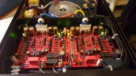
Here is what I did :
I squeezed the connection to the screw tranformers between two bolts.
I'll scratch the chassis as you suggested to ensure electrical contact between all the pieces of the chassis.
Each screw is connected to chassis, but :
- it's in the silicon part of the transformers, so there is no electrical contact between the transformer and the chassis (except shielding, see below)
- it's connected to the metalical part of the diode rectifiers. I don't know if that's a problem, but I can use plastic screws if needed.
Here is what I did :
An externally hosted image should be here but it was not working when we last tested it.
I squeezed the connection to the screw tranformers between two bolts.
I'll scratch the chassis as you suggested to ensure electrical contact between all the pieces of the chassis.
remove the earth connected to the bolt on the transformer.
remove connector strip.
connect eyelets to the IEC socket earth and transformer shield wire ends and then attach eyelets to a nut/bolt on the case using a crinkle washer so it bites into the alloy/metal (scrape away any anodising around the bolt hole both sides)
dont connect the boards GND to the case unless you get a hum. if you get a hum you are best to isolate using a bridge rectifier network.
** this is presuming that your house has a PE (Protective Earth) on the mains (wall sockets) **
your not joining the Earths as such but Earthing the case for safety reasons (PE)
Thank you, it's once again very clear. And my thanks too to everybody who is commenting this i really helping.
I'll do what you suggest, more things to order then !
Still, to try to understand : what was wrong with what I did ? since I think that from an electrical point of view we have the same connections. Is it because the bolt might not be fully connected to the chassis ?
(by the way my flat has PE)
I'll do what you suggest, more things to order then !
Still, to try to understand : what was wrong with what I did ? since I think that from an electrical point of view we have the same connections. Is it because the bolt might not be fully connected to the chassis ?
(by the way my flat has PE)
i'll try and draw something up later.
there is a discussion somewhere in this thread about using a bridge rectifier network for isolating the GND and PE.
looking at your picture.. are you sure that you have wired up the volume attenuator properly as mine gave me a fair bit of head scratching at first.
there is a discussion somewhere in this thread about using a bridge rectifier network for isolating the GND and PE.
looking at your picture.. are you sure that you have wired up the volume attenuator properly as mine gave me a fair bit of head scratching at first.
By bridge rectifier you mean ground loop breaker ? In another amp I build they use 10Ω 5W resistor in parallel with a 0.1µF capacitor rated at least 250VAC.
As for the attenuator I guess it's okay since it's work
I have :
- IN connected to RCA +
- OUT connected to IN+ in the amp board
- ground connected to IN - in the board and RCA ground
It's quite easy on this one since 3 different wires (per channel) are already attached to the attenuator.
As for the attenuator I guess it's okay since it's work
I have :
- IN connected to RCA +
- OUT connected to IN+ in the amp board
- ground connected to IN - in the board and RCA ground
It's quite easy on this one since 3 different wires (per channel) are already attached to the attenuator.
yup thats right.
yup a ground loop breaker using a bridge rectifier. but you might not need it. try disconnecting the Sapphire boards GND from Earth/case first (lifting the ground).
all joining faces of the case (top/bottom/sides/front/back) need to have some anodising removed on opposing faces so it has ''electrical'' contact. this ensures that the box becomes a 'shield'.
two other things i have done is. taken the IN- and moved it to the GND for the 'module'. i have also used 2core + shield for the input and connected the shield to the GND pin but you can also use the In- as well. doing this has resulted in to my ears.. silence.
my sapphire is now audibly silent but the RPi is now causing a hum when i plu it in so its a ground loop via the RPi and the Sapphire. personally i'm not that bothered as the hum goes away when i start playing music and its just the initial 'turn on' that is the problem.

Somewhere there exists a standard that manufacturers of electrical equipment must follow. I have read this in one of D. Self's book, and will try to find the true source. But to make a long story short, the earth ground must be connected to the chassis using a single connection which cannot be used for any other purpose. It must be made in such a way that it cannot come loose for any, including normal vibration, drop, heat, etc. Failure to provide a safe path for AC that has "escaped" could potentially be a matter of life and death.
In your build, you use the transformer bolt to both (1) secure the transformer and (2) provide an earth ground. Since this is for your own personal use, it is not wrong, just different. If it were my build, I would connect a very short piece of stout wire to a dedicated bolt that is ONLY used for earth ground, and nothing else. It would use lock washers, star washers, two nuts "cinched tightly together" like a "jam" nut, a locking nut, as much as I could find, as shown by Bibio. More is better. But it's not my build.
The second issue is whether or not to connect the amplifier ground to the earth (chassis) ground. That is a design decision to be made by you. I can only say that in the amps I have built to date (more than 2) I have chosen not to connect the amplifier ground to the earth (safety) ground, and to date have not had a problem. I use isolated input/output connectors, and the transformer secondary is filtered and then connected to the amplifier (PCB) ground but not to the AC earth ground. As mentioned by Bibio, I have also read that a R||C is good for breaking ground loops, but would add that only if needed.
As always, YMMV, void where prohibited by law, batteries not included, etc.
But to make a long story short, the earth ground must be connected to the chassis using a single connection which cannot be used for any other purpose. .... In your build, you use the transformer bolt to both (1) secure the transformer and (2) provide an earth ground. Since this is for your own personal use, it is not wrong, just different. ....
It's not only wrong, it's also dangerous. Normally, you are correct, it's personal use you don't have to build it to code, but attaching it to the bolt which fixes the toroidal transformer is a total no-no because it makes an electrical connection through the center of the toroid, creating the possibility (were another connection made between earth and chassis) of a shorted turn.
The second issue is whether or not to connect the amplifier ground to the earth (chassis) ground. That is a design decision to be made by you...
Here, this amounts to deciding whether to connect GND to the chassis directly, through a "humbuster", or not at all. Directly is best, but will only be successful is the audio circuit common has no other direct connection to earth (in the source, preamp, elsewhere).
One way to wiggle out of this is to use an external power supply and leave the amplifier chassis with no earth connection. it amounts to a ground lift but since there is no 120/240V AC wiring now in the amplifier chassis safety concerns are mitigated.
I have read this in one of D. Self's book
Found it.
"Audio Power Amplifier Design", 6th Ed., Douglas Self, 2013.
Chapter 25, Layout, Grounding and Cooling, pp. 602-607.
Chapter 29, Testing and Safety, pp. 686-694.
...the audio circuit common has no other direct connection to earth (in the source, preamp, elsewhere)...
Good point, I had not thought about that. I use a FIIO player, this amp, and headphones. I do not use other AC powered components such as computer, DAC, CD player, etc., and just did not consider that case.

For now it's not connected to anything, I've justed tapped the wires to isloate them from anything.
I'll try this way and if I hear a "hum" I'll try to connect them to the chassis, using another dedicated screw.
Well that is if I have correctly understood what everyone told me
I'll try this way and if I hear a "hum" I'll try to connect them to the chassis, using another dedicated screw.
Well that is if I have correctly understood what everyone told me
- Home
- Amplifiers
- Headphone Systems
- RJM Audio Sapphire Desktop Headphone Amplifier