For transformer noise, best way is transformers in separate chassis.
Knowing what I know now, I definitely agree ... but ... there is a convenience factor to consider. I suggest maybe the best compromise is to put them in a partitioned chassis some physical distance from the Sapphire boards. Worse case you have to line the partition dividers with mu metal. Of course separates are fine too, if you don't mind the clutter.
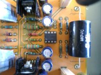
Rev. 1.4S1 with LME49710
Mood today my sapphire with xr7 0.1 uF ceramics as recommended in post
#77 http://www.diyaudio.com/forums/head...esktop-headphone-amplifier-8.html#post3043225
The soundqualität with LME49710 is very analytically, strong bass, good voices. Fantastic channel sepertion.
I am more than satified.
Regards
Attachments
Re: Sapphire v3
V 3.0 boards you can get:
RJM Audio - Printed Circuit Boards
RJM Audio - Sapphire headphone amplifier
Regards
V 3.0 boards you can get:
RJM Audio - Printed Circuit Boards
RJM Audio - Sapphire headphone amplifier
Regards
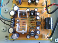
Update V1.4S1 boards
RE: http://www.diyaudio.com/forums/head...sktop-headphone-amplifier-97.html#post4707514
After hearing more hours with ceramics the most change are in analytically,
microdetail even in low level.
I think it is importend for this high bandwith amp.
I used Hifimediy Sabre U2 Asynchronous DAC ES9023 with
SA9023 USB receiver and listening flac files.
Also Technics SL-PS700 CD-Player both connectet to
sapphire V1.41s powered from one 50 VA toroidal transformer
with my Beyerdynamic DT-911.
Regards
If i have time i will make the v3.0 boards too.
V 3.0 boards you can get
You are correct, I do have recent v3.1n boards. I honestly did not remember the CCS, but checked the board and the schematic and sure enough, they are there. What can I say, working from memory again.
If i have time i will make the v3.0 boards too.
Sapphire3 boards are drop in replacement for the 1.4s boards you have.
There are two advantages, about 20 dB higher PSRR as a result of the CSS, and lower distortion due to the improved output stage.
/R
As a bit of an update and statement of intent, I've prepared a set of rev. 31n boards so that I can try out a 2520 discrete opamp, the Sonic Imagery Labs Model 995FET-Ticha.
The modules are on order, I'll update when they show up and I have a chance to get it up and running.
To recap, the main problem with using discrete modules in the Sapphire circuit is the high output offset voltages. Modules with bipolar inputs are generally going to be unsuitable - input offset currents are too high. JFET inputs though, should be okay.
The other thing you have to watch is the increased power draw compared to ICs. The model 995 runs 25 mA or so, 5-6 times more than an IC. The total circuit current increases from about 45 mA to 70 mA, but the voltage regulator components should be able to take that in stride.
Finally, a small compensation capacitor across the feedback resistor R3 may be needed for best performance. This will depend a little on the gain setting and the value of the feedback resistor, but is expected to be in the order of 100-150 pF. The datasheet doesn't give a recommended value.
P.S. The datasheet and specs overall seem solid, with plenty of measurements to back up the numbers. I will ding them a point for the part where they claim "The enhanced low distortion Class-A output driver stage can sink or source 250mA". No. If your package draws less than 25 mA idle total, you cannot output 250 mA from a class-A stage without it going into class B operation. If fact, the class-A output current will be limited to something in the order of 25 mA. That's still plenty, and way more than needed for driving the Sapphire output buffer, but as a claim it rankles.
Attachments
Last edited:
At $140/pair, those better be REALLY great-sounding op-amps.
Personally, I've not heard many plastic JFET op-amps that sound as good as some of the better bipolars. Granted, I haven't tried any discrete op-amps...JFET or bipolar.
I look forward to your listening impressions.
Personally, I've not heard many plastic JFET op-amps that sound as good as some of the better bipolars. Granted, I haven't tried any discrete op-amps...JFET or bipolar.
I look forward to your listening impressions.
To be honest, I am doing this in the spirit of experimentation. Going in I don't think there is going to be a huge benefit over the OPA134 or NE5534 in the Sapphire circuit. That's because the chief advantage of discrete is the high-current output stage you can implement, and that isn't of great use here since the op amp is bolted to a high-current discrete buffer anyway!!
However, there is pretty consistent anecdotal reports that they sound better, so I'm up for giving it a shot. As time passes my Sapphire is getting more and more gilded. First the Goldpoint attenuator ($150, ching!) then the Furutech RCA jacks ($60, ching!), and now these...
However, there is pretty consistent anecdotal reports that they sound better, so I'm up for giving it a shot. As time passes my Sapphire is getting more and more gilded. First the Goldpoint attenuator ($150, ching!) then the Furutech RCA jacks ($60, ching!), and now these...
That's because the chief advantage of discrete is the high-current output stage you can implement, and that isn't of great use here since the op amp is bolted to a high-current discrete buffer anyway!!
That's what I was kind of thinking, but I didn't want to say anything.
")
I've tried op-amps(like some of the NJR offerings) that others here have written off as garbage and been quite surprised by their sound quality in the right application(s).
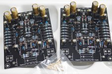
The Sonic Imagery Labs 995FET-Ticha 2520 modules arrived and I have them installed and working in the Sapphire 31n boards.
The datasheet offset specs are 1 mV (2.5 mV max) and 200 pA. At the working impedances the offset current is irrelevant and the predicted output offset voltage is (max) 2.5 mV x [gain = 20 in my case] so about 50 mV worse case, plus whatever the buffer contributes.
I measure about 40-50 mV both channels at the buffer output, just a tad more than the 20-30 mV I get with the OPA134. Unlike the various bipolar modules disfunctionalshadow tried earlier I am happy to report that the 995FET is plug-and-go.
The modules are pretty neat. A bunch of SMT components on a small board, with some metal bracket heatsinks and the plastic cover. Each one appears to be hand tested.
More later. The modules and the boards are in break-in.
P.S. When testing the boards I discovered I had mixed up the 4.75 and 4.75k ohm resistors. Aargh! Fortunately my trusty-dusty de-soldering tool came to the rescue and the repair went smoothly enough. The photo I posted earlier had the wrong resistor values, just so you know.
P.P.S The gold sockets for the modules are a little smaller than the mounting holes on the board. The best way to solder them is to plug the 6 individual sockets on the module first, then set the module and sockets into position on the board and solder the sockets. This insures that all the sockets line up properly with the pins in the module.
Attachments
Last edited:


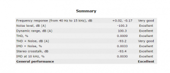
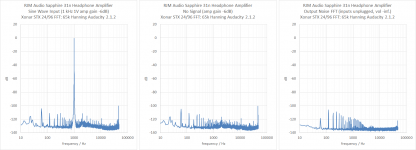
Sapphire 31n with 995FET modules, amplifier gain ~26 dB.
Rightmark RMAA data, unity gain, unloaded. Measurements using Xonar STX at 24/96.
This is the first time the Sapphire has cleared 100 dB in rightmark noise benchmark! Previous best was -96 dB. (The gain of the new version is 1-2 dB lower, accounting for some but not all of the difference.)
Rightmark RMAA data, unity gain, unloaded. Measurements using Xonar STX at 24/96.
This is the first time the Sapphire has cleared 100 dB in rightmark noise benchmark! Previous best was -96 dB. (The gain of the new version is 1-2 dB lower, accounting for some but not all of the difference.)
Attachments
Last edited:
Sapphire 31n with 995FET modules, amplifier gain ~26 dB.
Rightmark RMAA data, unity gain, unloaded. Measurements using Xonar STX at 24/96.
This is the first time the Sapphire has cleared 100 dB in rightmark noise benchmark! Previous best was -96 dB. (The gain of the new version is 1-2 dB lower, accounting for some but not all of the difference.)
That's some good measurement results, although at a significant upgrade cost. What is the FFT size that was used?
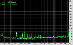
I don't know what RMAA defaults to, 16k I suspect. Separate measurement with audacity 65k Hanning shown below confirms the same values.
If you want to check with your own software you can download the recorded output signal I used for the FFT below here.
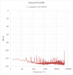
The harmonics at 120Hz-1khz are picked up from the Sapphire power transformers. The junk at 10kHz is computer crud unrelated to the Sapphire amp. The recorded noise baseline is that of the Sapphire, not the Xonar soundcard. Seems to be -135 dB-ish. To the best on my knowledge the soundcard is calibrated to record 1 Vrms input as 0 dB with the line in volume at 100% so the FFT y-axis scale (dB) should be correct.
If you want to check with your own software you can download the recorded output signal I used for the FFT below here.
The harmonics at 120Hz-1khz are picked up from the Sapphire power transformers. The junk at 10kHz is computer crud unrelated to the Sapphire amp. The recorded noise baseline is that of the Sapphire, not the Xonar soundcard. Seems to be -135 dB-ish. To the best on my knowledge the soundcard is calibrated to record 1 Vrms input as 0 dB with the line in volume at 100% so the FFT y-axis scale (dB) should be correct.
Attachments
Last edited:
Yes, I checked and the soundcard is properly calibrated.
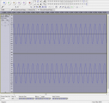
A 1 V amplitude sine wave tone in audacity will output as 2 V rms, and 2 V rms input will be recorded as a 1 V amplitude signal in audacity.
I set the volume on the Sapphire to produce -6dB attenuation (the 1 V sine wave is recorded as a 0.5 V sine wave, see attached screenshot). For your reference, the Sapphire amplifier gain is 26 dB, so -6 dB means the volume control attenuation was set to -32 dB.
The FFT shows the 1 kHz peak at 0 dB. This is correct because the input signal is in both channels, giving twice the signal for a 6 dB boost. By the same logic the FFT shows the noise baseline at 3 dB lower than the value it would be if only one channel of data was being analyzed, due to noise averaging.
There is slightly more noise with the inputs plugged in than with them unplugged. This could be due to several different factors and is not really a big concern.
Attachments
Last edited:
The estimated noise baseline is therefore -135 dB (from inputs unplugged measurement), giving an input-referred noise figure of + 3 dB - 26 dB = -158 dB or 12 nV/rt Hz.
The op amp modules have an impressive noise figure of 1.1 nV/Hz, but I would not expect the headphone amplifier in total to return that number.
The op amp modules have an impressive noise figure of 1.1 nV/Hz, but I would not expect the headphone amplifier in total to return that number.
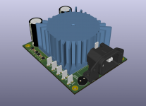
Sapphire PSU PCB
I'm finally getting around to my Sapphire build. As mentioned before, I wanted to use it as an excuse to layout a PCB based around a PCB mounted transformer. I'm nearly done tweaking with it as much as I can and the KiCad design files are up on GitHub: https://github.com/gregose/oal-sapphire-psu. Renders and schematic are in the /docs directory. I have a work in progress BOM at DigiKey at http://www.digikey.com/short/3mr3zp.
Some features are listed below:
- Same footprint (80x100mm) as the Sapphire
- Through hole IEC and fuse
- FASTON / quick connect tabs for wiring a chassis mounted power switch and configuring primary transformer wiring for 120 or 240v
- 25VA transformer
- 2 discrete SMD diode bridges. Each diode individually bypassed
- Up to 16mm smoothing caps per rail (5 or 7.5mm lead spacing)
- LED indicators for each rail
- Two 3.5 pitch terminals for each rail and ground
I would love any feedback or suggestions on this design. It's been fun tweaking and obsessing over the layout, but I guess I should make sure it will actually work well for the Sapphire
Attachments
- Home
- Amplifiers
- Headphone Systems
- RJM Audio Sapphire Desktop Headphone Amplifier