The photo shows the copper (brass?) bands I first installed. With the mu-metal what I actually did was put a strip of the same dimensions underneath the copper band. So you wouldn't see any visible change. (Essentially the copper band became a "former" so make it easy to get the shape from the mu metal, which is only 0.1 mm thick and more easily bent out of shape.)
That was just convenience, the original band were already the right dimension, and held the mu metal in place without getting messy with the adhesive back.
That was just convenience, the original band were already the right dimension, and held the mu metal in place without getting messy with the adhesive back.
There is no need to use parallel transistors, the you will find you get into problems using much larger transistors for the output than the input in a diamond buffer.
There's no V_be multiplier in the circuit to control the output bias current, in a diamond buffer the input bias current determines the output bias current. There is a small amount of modification by the "hack" of adding R9,10 into the circuit, but these resistors must be kept very small or performance degrades significantly.
There's no V_be multiplier in the circuit to control the output bias current, in a diamond buffer the input bias current determines the output bias current. There is a small amount of modification by the "hack" of adding R9,10 into the circuit, but these resistors must be kept very small or performance degrades significantly.
There is no need to use parallel transistors, the you will find you get into problems using much larger transistors for the output than the input in a diamond buffer.
There's no V_be multiplier in the circuit to control the output bias current, in a diamond buffer the input bias current determines the output bias current. There is a small amount of modification by the "hack" of adding R9,10 into the circuit, but these resistors must be kept very small or performance degrades significantly.
Okay, I'll keep it that way, one more question ...
Why not use the negative feedback direct opamp the output?
Another build
Richard,
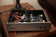
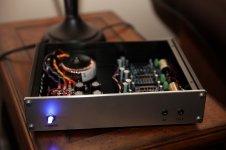
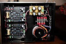
Thought you might like to see pics of your boards in action. Have had the boards for some time, and have been procrastinating about doing something with them. Decided that this weekend was time to actually do something.
The chassis was purchased on ebay over a year ago. The project I had targeted failed to materialize, so it was a problem in search of a solution. The board fit nicely, with room for the other stuff.
I make one change, decided not to use 4 bridge rectifiers, instead choosing fast Schottky diodes, a reservoir, then an R-C (pi) filter.. There is less than 1mV ripple into the boards, and ripple is in the noise at the opamp.
I hope saying this does not start a holy ward, but I like this amp over the Marsh amp for 2 reasons: (1) DC offset is a non-problem with this design, and (2) heat? what's that? The sound quality between them is very close, though. My ear thinks the highs are just a bit cleaner, but that may supply-related.
Thanks for the boards!
Mike

Richard,
Thought you might like to see pics of your boards in action. Have had the boards for some time, and have been procrastinating about doing something with them. Decided that this weekend was time to actually do something.
The chassis was purchased on ebay over a year ago. The project I had targeted failed to materialize, so it was a problem in search of a solution. The board fit nicely, with room for the other stuff.
I make one change, decided not to use 4 bridge rectifiers, instead choosing fast Schottky diodes, a reservoir, then an R-C (pi) filter.. There is less than 1mV ripple into the boards, and ripple is in the noise at the opamp.
I hope saying this does not start a holy ward, but I like this amp over the Marsh amp for 2 reasons: (1) DC offset is a non-problem with this design, and (2) heat? what's that? The sound quality between them is very close, though. My ear thinks the highs are just a bit cleaner, but that may supply-related.
Thanks for the boards!
Mike
Attachments
Hi Mike, thanks indeed for the pics... looks very ship-shape.
No problems with magnetic interference from the transformer then? Why is it just me!?
Just by the way, with your CRC filter what value of resistor did you choose? While I don't think the choice of diodes (or bridge) will make much difference it might be worthwhile to experiment a little with the filter. I mean at the level of with/without or possibly just with extra capacitance and no resistance. I don't know which is better, necessarily.
No problems with magnetic interference from the transformer then?
None that I can hear. That does not mean it's non-existent. Once upon a time an old-timer told me that if you could not hear it, it was 60db down or better. But that was a long, long time ago, the number may be wrong.
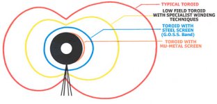
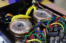
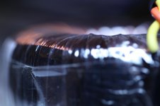
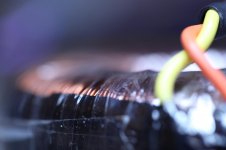
I've been following the mu-metal discussion on this thread closely, and I think the lack of EMI is mostly luck. I'm using a Triad VPT series transformer from mouser, and I think it may have a goss shield, belly band, permalloy, mu-metal, etc. See pics. I can see a darker gray band of something thin wrapping the entire outer circumference of the transformer. I've checked the Triad website and they make no mention either way. I've sent in a "request for info" asking what this is, we'll see if they respond.
I also lucked out when I used an over-sized transformer. The VPT24-1040 is rated 2x12 at 25VA, massive overkill. No-load DC voltage at the first reservoir is 20V (give or take). The two boards draw 100ma from each rail, dropping DC voltage to 18.5V. At 100ma, a 33R resistor drops another 3.3V, leaving voltage to the board at 15V. I think 5V headroom for the on-board regulator is good and that's where I left it.
All things considered, I had a bit of good luck on this build. I'll do more AC noise measurements when the new/cool factor wears off.
Attachments
Casually speaking, -60 dB is about the level of hum you can stand in a tube amp. Ripple/noise in a headphone amp, you can hear to about -80 dB depending on the sensitivity of your headphones of course. The Sapphire output noise floor is about -134 dB. I believe noise spikes down at -100 dB or even lower, even while not perceptible directly as noise, do influence the sound quality as a loss of spacial detail or clarity at the lowest levels of resolution.
I have a bunch of those Triad tranfsormers. I am pretty sure that's just black plastic tape used to hold and cover the leadout wires temporarily before the clear plastic wrap is wound over the hole unit. Magnetic shields are very similar, but look more obviously like a stiff metal belt.
I have a bunch of those Triad tranfsormers. I am pretty sure that's just black plastic tape used to hold and cover the leadout wires temporarily before the clear plastic wrap is wound over the hole unit. Magnetic shields are very similar, but look more obviously like a stiff metal belt.
Last edited:
The Sapphire output noise floor is about -134 dB.
Sounds to me too low to be true as a full bandwidth noise measurement - is this figure plucked from an FFT plot by any chance? If it is then the measurement bandwidth can be determined from the FFT parameters - it will be a very small fraction of the full audio band.
I am pretty sure that's just black plastic tape used to hold and cover the leadout wires temporarily...
Well shoot. Where did you find copper bands?
I recommend buying a permalloy (mu metal) sheet off ebay. You can cut it with scissors, it has adhesive backing, or you can hold it in place with a cable tie.
auction link
auction link
- Home
- Amplifiers
- Headphone Systems
- RJM Audio Sapphire Desktop Headphone Amplifier