Q. if i took some two core microphone cable and used the two cores for hot/cold then connected the screen to GND on the boards would that screen the cable from interference?
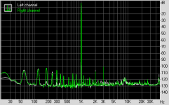
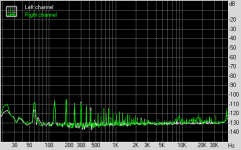
well that worked really well. i got a reduction of around -6db so now sitting around -86db@50hz. i can now touch the input cables and the 50hz does not move where before it would rocket to around -50db@50hz. plot looks a lot cleaner as well with less spikes, i now have no spike at 100hz, -90db@150hz and getting smaller every 50hz till around the 400hz then pretty much nowt all the way up to 20k. 1k-20k i'm getting a pretty flat -120db to -123db.
still getting a really weird ripple though.
next up i'll try taking the daughter boards off the rectifiers and wire them direct.
Today I got around to measuring the distortion under a test load. I haven't been too concerned to do it before now as I was pretty confident in the simulation.
The measurements indeed confirm the simulation, within a factor of two.
Test conditions 47 ohms -3dB FS (0.7 Vrms 1 V amplitude). This is 10 mW per channel, about the maximum you would ever apply to a headphone in real life.
Measured THD 0.0016 % (-95 dB). Simulated result gives about -110+6+3 = -101 dB or 0.0009%.
While the results will be slightly worse for very high or very low load impedances (47 ohms is close to he optimum design point.) I'd still like to brag a little:
The Sapphire3 headphone amplifier, with no feedback in the output buffer, achieves <0.002% THD at 10 mW.")
The unloaded THD is 0.0009%. The noise floor, incidentally, is equivalent to an input referred value of 8 nV/sqrtHz, exactly the datasheet value for the OPA134. In other words apart from the harmonic spikes I've hit bottom as far as the baseline noise is concerned.
@Lance Keep at it! Shielding cables is on my to-do list, but first I'm going to install the permalloy (mumetal) sheet I bought on ebay around the transformers.
The measurements indeed confirm the simulation, within a factor of two.
Test conditions 47 ohms -3dB FS (0.7 Vrms 1 V amplitude). This is 10 mW per channel, about the maximum you would ever apply to a headphone in real life.
Measured THD 0.0016 % (-95 dB). Simulated result gives about -110+6+3 = -101 dB or 0.0009%.
While the results will be slightly worse for very high or very low load impedances (47 ohms is close to he optimum design point.) I'd still like to brag a little:
The Sapphire3 headphone amplifier, with no feedback in the output buffer, achieves <0.002% THD at 10 mW.
The unloaded THD is 0.0009%. The noise floor, incidentally, is equivalent to an input referred value of 8 nV/sqrtHz, exactly the datasheet value for the OPA134. In other words apart from the harmonic spikes I've hit bottom as far as the baseline noise is concerned.
@Lance Keep at it! Shielding cables is on my to-do list, but first I'm going to install the permalloy (mumetal) sheet I bought on ebay around the transformers.
Attachments
Last edited:
Today I got around to measuring the distortion under a test load. I haven't been too concerned to do it before now as I was pretty confident in the simulation.
The measurements indeed confirm the simulation, within a factor of two.
Test conditions 47 ohms -3dB FS (0.7 Vrms 1 V amplitude). This is 10 mW per channel, about the maximum you would ever apply to a headphone in real life.
Measured THD 0.0016 % (-95 dB). Simulated result gives about -110+6+3 = -101 dB or 0.0009%.
While the results will be slightly worse for very high or very low load impedances (47 ohms is close to he optimum design point.) I'd still like to brag a little:
The Sapphire3 headphone amplifier, with no feedback in the output buffer, achieves <0.002% THD at 10 mW.
The unloaded THD is 0.0009%. The noise floor, incidentally, is equivalent to an input referred value of 8 nV/sqrtHz, exactly the datasheet value for the OPA134. In other words apart from the harmonic spikes I've hit bottom as far as the baseline noise is concerned.
@Lance Keep at it! Shielding cables is on my to-do list, but first I'm going to install the permalloy (mumetal) sheet I bought on ebay around the transformers.
Great results!
But most audio interfaces headphone outputs are already 10mW per channel. And really little, it misses one more, understand?
I did the simulation:
R11 and R12 to 680 ohms.
R3 and R4 to 100 ohms.
Evident that consumption is doubled, but with more power without compromising distortion.
Am I right or I do it differently?
@abraxalito Yes, I know to keep handle it as gently as possible, but I will have to cut it into strips regardless. I was thinking I could reanneal it after forming, but apparently it has to be done in a dry hydrogen atmosphere which I do not want to mess about with due to the explosion risk.
@felipeunix Changing R3,4,11,12 (ltspice schematic, above) adjusts the bias currents. Using 100 ohms / 680 ohms triples the bias in Q9-18 from 33 mA to 100 mA total, so the distortion : output power curves shift upwards proportionately. The change you suggest also reduces the quiescent current to Q7,8 to 1 mA however, a bit lean to drive 5x20 mA Q9-18 (0.2 mA quiescent base current) though the simulated distortion indicates improvement. Q9-18 now dissipate 220 mW each, which will increase the temperature 35 C above ambient.
TL;DR : The as-designed operating points of the Sapphire3 are conservative, you can "overclock" it up to about 100 mA without major drawbacks if you want.
Formally the stock Sapphire3 output power is about 100 mW 16-300 ohm, if the distortion limit is relaxed to 0.1%. My obsession with 10 mW is as a "realistic maximum" for which the distortion would still be relevant. My design goal there was 0.001% THD (-100 dB) at 60 ohms : 10 mW, while measurements confirmed 0.0016% / 47 ohms. Close enough, as far as I am concerned.
Last edited:
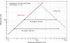
I've posted similar data before, but to recap and with a new graphic:
The output power defined by 0.1% THD (threshold of hard voltage clipping, or the output stage transitioning to class B operation) depends on the headphone impedance. Between 35 and 500 ohms, at least 100 mW is on tap, while the specification must be reduced to 45 mA to cover the full range of headphones between 16 ohms and 600 ohms.
The deeper you are under the red "hat", the lower the distortion will be, with the Sapphire's optimal headphone impedance being about 60-300 ohms.
When listening to music with either my HD600 or K702 cans, I'm not even on this plot. The maximum (source 0dB) output power at my listening volume position (it works out to 95 dB SPL) is 0.6 mW for the HD600 and 1.6 mW for the K702s with the actual average music power about 10 times less. So while 100 or 200 mW output might look nice on paper, it is irrelevant to the problem at hand, which is how good the amp can make <10 mW sound like.
Attachments
Last edited:
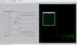
i'm confident that i have tracked the problem down to my power supply causing the ripple.
i removed the daughter boards from the rectifiers and still no joy. i swapped the MK2 boards back in and still no joy. so next up is removing the power switch from the power supply and see what happens if still no joy then its either the transformer or the bridge rectifiers.
i removed the daughter boards from the rectifiers and still no joy. i swapped the MK2 boards back in and still no joy. so next up is removing the power switch from the power supply and see what happens if still no joy then its either the transformer or the bridge rectifiers.
You mean, I guess, the source of the residual noise when the RPi is taken out of the equation. It could be the transformers, but don't you have an external power supply?
To avoid going on a wild goose chase, I suggest double-checking the loop-back noise to make sure it isn't just garbage generated by the soundcard or picked up by the cables. In other words, disconnect the test signal feeding the headphone amp and connect it instead straight into the soundcard and remeasure to get a feel for the baseline sensitivity of the test setup.
To avoid going on a wild goose chase, I suggest double-checking the loop-back noise to make sure it isn't just garbage generated by the soundcard or picked up by the cables. In other words, disconnect the test signal feeding the headphone amp and connect it instead straight into the soundcard and remeasure to get a feel for the baseline sensitivity of the test setup.
who's a clever clogs.. Richard is
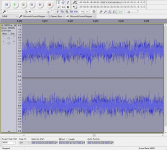
recorded on the laptop running on battery power
dont know what the amplification is as the laptop has a seriously rubbish sound card but i boosted it up just to show there is no ripple.
so the ripple has been my main desktop soundcard all this time.
recorded on the laptop running on battery power
dont know what the amplification is as the laptop has a seriously rubbish sound card but i boosted it up just to show there is no ripple.
An externally hosted image should be here but it was not working when we last tested it.
so the ripple has been my main desktop soundcard all this time.
? why would reducing the gain on the opamp result in change of sound quality.
i have changed R1-100k, R2-1k, R3-10k. prior to this i removed C1, R1 and C23-24. the result is a lot smoother sound especially in the vocals and less aggressive sound overall. still goes plenty loud enough to not want full volume. if i was listening around 2oclock its now around 3oclock.
i have changed R1-100k, R2-1k, R3-10k. prior to this i removed C1, R1 and C23-24. the result is a lot smoother sound especially in the vocals and less aggressive sound overall. still goes plenty loud enough to not want full volume. if i was listening around 2oclock its now around 3oclock.
To answer the question directly, changing the op amp closed loop gain alters both the distortion and noise figures directly in proportion to the change in feedback (open loop gain - closed loop gain). The higher the closed loop gain, the worse the performance.
Meanwhile, changing the (digital) volume control in the source to compensate will also affect the noise and distortion there too, though its a more complex relationship. Typically it will sound cleaner at higher volumes.
Just a note: its harder to follow your experiments than perhaps you imagine. You didn't tell us, for instance, what the change in gain was, or even what the resistor values were before you made the change.
I have no info on noise, but it is unlikely to affect the circuit since the output noise floor is determined by the op amp not the output buffer.
BC639/640 look like BC327/337 but rated to slightly higher voltages. I expect them to be rather similar in performance.
Important note: these are ECB TO-92 packages and not CBE like the BC327/337 so don't use them as a drop in replacement on my boards!! (you can carefully rotate the packages to align the correct pins if you know what you are doing though)
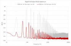
Permalloy sheet (via ebay) cut into strips and wrapped around the transformers.
Effective!
(note: Audacity screencap is displayed at 80dB gain now rather than 70dB, since the noise is so much less.)
Effective!
(note: Audacity screencap is displayed at 80dB gain now rather than 70dB, since the noise is so much less.)
Attachments
Last edited:
that looks a loooot better.
i suppose in hindsight i should have got troidy to wrap my trafos with mu-metal instead of just a band. hhhmm there's a thought i wonder if i made up some top/bottom hats out of mu-metal it would work the same due to there already being a band.
i suppose in hindsight i should have got troidy to wrap my trafos with mu-metal instead of just a band. hhhmm there's a thought i wonder if i made up some top/bottom hats out of mu-metal it would work the same due to there already being a band.
- Home
- Amplifiers
- Headphone Systems
- RJM Audio Sapphire Desktop Headphone Amplifier