![IMGDEAD]](/community/proxy.php?image=http%3A%2F%2F%5BIMGDEAD%5Dhttp%3A%2F%2Fi59.tinypic.com%2F24x3vjc.jpg%5B%2FIMGDEAD%5D&hash=becc3b46bc5d1329fb5045cebaa179cd)
Thanks for the update and photos.
Does the gain switch work fine? I mean, no noise or interference? You are the first person so far to wire it externally like that.
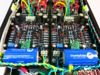
50VA are indeed a little crowded in there. I might have considered a staggered, rather than inline arrangement but there isn't much room front/back either. Looks like you managed OK though, just about.
Volume controls are a pain. My own Takman stepped attenuator (ebay) has a poor-quality rotary switch which is starting to lose contact force in the brush. I'm sure the Goldpoints are nice but sheesh that's a lot of cash for a *******' rotary switch and a few SMT resistors. So I'm still searching for something decent.
Does the gain switch work fine? I mean, no noise or interference? You are the first person so far to wire it externally like that.
Yes it works fine. Being able to switch between the 2 makes me feel that I could have lived with the fixed high gain with the HD380 and 650 cans. The female plugs are a bit of a loose fit but I got the wires a bit short so both are pulled up tight against the pins. There may be better plugs but now that I know it works I might just solder them on next time I open it up.
My daughters old sacrificial Sony headphones were used for initial testing and they need the low gain.
I'm looking in to getting an NOS Alps Black beauty pot from the swap thread. Any opinions on them? I don't think I like the stepped pots feel or jumps in volume.
I wasn't sure about the 50VA either but they were cheaper than the 35VA at the time so planned on making a dual power supply for the phonoclone if it failed.
kffern
Regarding pots, I had wanted to try a LDR volume but it won't fit and then finding a 12/5v supply as well.
I just bought some small LDR boards from Sachu888 who is on Lencoheaven, audiokarma etc. Now to find some sorted LDRs...
One day I might put the old sapphire boards into a larger case and give it a try.
kffern
I just bought some small LDR boards from Sachu888 who is on Lencoheaven, audiokarma etc. Now to find some sorted LDRs...
One day I might put the old sapphire boards into a larger case and give it a try.
kffern
R
I just bought some small LDR boards from Sachu888 who is on Lencoheaven, audiokarma etc. Now to find some sorted LDRs..
The boards are 55x55mm and contain 5v reg and mount the 100k pot.
kffern
Kffern, what's the part used for the switch plug (jumper)? (Is it a Mollex part?) Thanks.
Mine is from my local electronics hobby shope
http://www.altronics.com.au/p/s2035a-dpdt-centre-off-pcb-mount-miniature-slide-switch/
kffern
Sparko Labs' SS3601 discrete op amps in place of the OPA134's
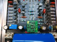
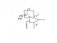
I discovered the hard way that these are not quite a drop-in replacement in the Sapphire design, as previous posts will describe. Andrew Sparks was quick to understand the problem and suggested a 2.2M resistor between Op Amp pin 3 and the 12V power rail. After some email discussion, instead, I installed a 5M Bourns 3299 trimmer on some vacant real estate on each Sapphire 3.0f board (between C16 & C18). Not the neatest installation, but it all seems to work. The one thing I’m still wondering about is that it took a long time for the output offset voltage to settle down - an hour. Even so, the values bobble around, sort of +/- 10 or 15 mV, but I set both channels so that each was about 15 mV, +/-. Voltage between op-amp pin 4 and 7 is 10.3 v, rather than 21 V with the OPA134's in place in my build (Richard's kit docs say to expect about 23V pin 4 to pin 7).
Sound is lovely, and with my very first test track I heard something I hadn’t heard before, and hearing it brought me to suddenly realize something about the sound of the OPA134. I’ve read people describe the Burr-Brown sound as dark and I have never perceived it that way - until I heard the SS3601 discrete op amp sing. It is different, I suppose it must be a bit brighter, for lack of a better description. Anyway, with more listening in the last couple of hours since powering it up, I’m extremely pleased with the sound. The OPA134's are not going back in.
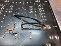
First image shows the underside of a board, with the pot wired between Op Amp pin 3 and the 12V rail at the end of R7 where there is a through-hole contact to the power rail on the top of the board. I used a Dremel diamond bit to cut through the copper foil to isolate the pot contacts from the ground on the board top and bottom.
I re-installed a 22pF cap across the feedback resistor; hedging my bets, really. It’s underneath the board and whether it’s needed or not I figured it wouldn’t hurt and I won’t have to take things apart again to install one if it is needed. I changed R4 to 18K, which matches the gain to my headphones (I had used Richard’s 22k in the kit as ‘close enough', but now the gain is matched to my phones' impedance.
Many thanks to Andrew Sparks for helping me make this work. Very impressed with the gentleman and his product.
I discovered the hard way that these are not quite a drop-in replacement in the Sapphire design, as previous posts will describe. Andrew Sparks was quick to understand the problem and suggested a 2.2M resistor between Op Amp pin 3 and the 12V power rail. After some email discussion, instead, I installed a 5M Bourns 3299 trimmer on some vacant real estate on each Sapphire 3.0f board (between C16 & C18). Not the neatest installation, but it all seems to work. The one thing I’m still wondering about is that it took a long time for the output offset voltage to settle down - an hour. Even so, the values bobble around, sort of +/- 10 or 15 mV, but I set both channels so that each was about 15 mV, +/-. Voltage between op-amp pin 4 and 7 is 10.3 v, rather than 21 V with the OPA134's in place in my build (Richard's kit docs say to expect about 23V pin 4 to pin 7).
Sound is lovely, and with my very first test track I heard something I hadn’t heard before, and hearing it brought me to suddenly realize something about the sound of the OPA134. I’ve read people describe the Burr-Brown sound as dark and I have never perceived it that way - until I heard the SS3601 discrete op amp sing. It is different, I suppose it must be a bit brighter, for lack of a better description. Anyway, with more listening in the last couple of hours since powering it up, I’m extremely pleased with the sound. The OPA134's are not going back in.
First image shows the underside of a board, with the pot wired between Op Amp pin 3 and the 12V rail at the end of R7 where there is a through-hole contact to the power rail on the top of the board. I used a Dremel diamond bit to cut through the copper foil to isolate the pot contacts from the ground on the board top and bottom.
I re-installed a 22pF cap across the feedback resistor; hedging my bets, really. It’s underneath the board and whether it’s needed or not I figured it wouldn’t hurt and I won’t have to take things apart again to install one if it is needed. I changed R4 to 18K, which matches the gain to my headphones (I had used Richard’s 22k in the kit as ‘close enough', but now the gain is matched to my phones' impedance.
Many thanks to Andrew Sparks for helping me make this work. Very impressed with the gentleman and his product.
Attachments
Thanks! Glad everything worked out for you. Thanks for your patience with these mods!
Stan or Sparko...just curious how the addition of the trimmers actually solved the offset problem?
I'm trying to picture the circuit with the trimmers in my head.

Thanks...
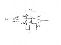
The offset was caused by input bias current. (few uA that flow into the input pins)
The POT simply supplies this current. Before the pot it was pulling it from an R to ground, so it dropped some voltage across that R, making the input not really ground, but slightly negative. The POT is tied to V+ to counter act the slight negative voltage, and bring it all back to zero.
The POT simply supplies this current. Before the pot it was pulling it from an R to ground, so it dropped some voltage across that R, making the input not really ground, but slightly negative. The POT is tied to V+ to counter act the slight negative voltage, and bring it all back to zero.
...how the addition of the trimmers actually solved the offset problem?...I'm trying to picture the circuit with the trimmers in my head...
There are others who would answer this more technically than I can, but my understanding of what I've done is that I've added a little over 2 megohms resistance between one of the Op Amp inputs (pin 3) and the power rail to equalize the impedance 'seen' by the two Op Amp inputs. There seemed to be some doubt about the precise value needed, so rather than experiment with different resistors, I installed an adjustable trimmer pot. Once the amp is up to temperature, by adjusting the trim pot you can set the output offset to the desired value, in this case about 15mV. I don't know if it's an audible difference, but my output bias measurements on both channels now match.
On the schematic, the trimmer is between pin 3 of the Op Amp and the power rail connected to the Q12 emitter. R7 is connected to that power rail on the top of the board, and through-hole it is isolated from the foil on the underside of the board. So I extended a wire from one side of the trimmer to that end of R7 on the underside of the board. The location of the trimmer is just one of convenience (ie. where the space exists for it); I had to isolate the trimmer pins from the foil on both sides of the board at the trimmer location I chose, I used a diamond bit on a Dremel tool to cut the foil. On the topside, I removed foil from around the holes drilled; on the underside, I cleaned the black paint off the foil around the holes for soldering the pins. Then I cut a 'moat' around the soldered pins to isolate them. Note that there is also a moat cut through the foil between one terminal pin and the connected wiper and other terminal pin. The trimmer is connected to Sapphire circuitry only by the wires added to the backside of the board.
One has to connect the trim pot wiper and one of the trimmer terminals to use it inline like this.
The pot doesnt really equalize the impedance as seen by the inputs - though that is one way to remedy an input bias current induced offset.
its rather that we created a voltage divider to force the + input to be near 0V. The minus input was already pretty close to 0V since it has like a 100 ohm to GND.
its rather that we created a voltage divider to force the + input to be near 0V. The minus input was already pretty close to 0V since it has like a 100 ohm to GND.
- Home
- Amplifiers
- Headphone Systems
- RJM Audio Sapphire Desktop Headphone Amplifier