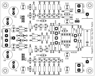
Sapphire 3.1n boards are goooooooooooo. Should have them here in two weeks.
Attachments
Thanks for your comment.
So you want a switch to bypass the volume control and voltage amplifier parts the Sapphire? Is that right?
I am thinking of offering the buffer circuit of the Sapphire as a standalone board, possibly with voltage regulation but most likely without. Would that be of any interest? You could add it more conveniently to existing equipment like preamps, or mix or match power supplies and voltage amplification as you like. It could be set up as a line buffer or headphone driver, depending on the configuration.
Trying to put in a jumper/switch between the op amp and buffer is doable, but I'm not sure enough people would be interested to warrant the additional complication that everyone who didn't want to use the feature would now have to wire a shorting jumper.
Hi Richard,
That sounds like a good option I was thinking about modular set up like this !
Just received J amp kit and sapphire boards v 3.0 tempted to start the project.
Thank you so much.
Btw a question in J amp boom there is 100 va transformer specified, while sapphire requires 2x25 va meaning power consumption is expected Ed twice less is that right ?
Last edited:
Hi Oleg,
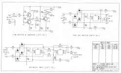
What you are asking for would require the following,
1. Circuit for the balanced->unbalanced conversion.
2. Circuit for the unbalanced->balanced conversion.
3. Four Sapphire amplifier boards.
4. Modification of headphones to use a four pin socket.
Parts 1,2 are generic audio design blocks and don't specifically relate to the Sapphire. You could could make your own, or I imagine they could be sourced from somewhere. An example circuit is attached, FYI.
Attachments
Hi Richard,
Lately I have been evaluating an idea of enriching my current setup by adding a pair of Sapphires. Since I am a newbie to DIY audio business, I would rather consult with you on several issues which apparently are not obvious to me (and maybe silly/trivial to you), before I give it a go. I hope you don't mind a lengthy post.
My plan is to put the amp between dam1021 DAC and Beyerdynamic DT 880. The basic specs of DAC: unbalanced Vout = 1.4Vrms (0V offset), Zout = 625Ohm (simply it is a voltage source); the cans as claimed by vendor: R = 600Ohm, sensivity 96dB SPL (don't know whether per mW or 1Vrms, so useless). But I found a spreadsheet [1] that claims these cans exhibit R = 619Ohm, and sensitivity around 94dB/mW. Let's stick to those. Volume control will be handled by DAC in digital domain.
1. Calculating gain.
I'm interested in getting 115 dB SPL at peaks. Using the gain calculator attached to the BOM spreadsheat I've got 33dB which differs somewhat from my calculations. According to [1] I need 10.28 Vrms, so gain = 20*log(10.28/1.4) ~= 17dB. Could you tell what 40.7-6 expression from formula at F5 cell stands for?
Occasionally I plan to use other low level impedance headphones (30-60 Ohm), so jumper gain switch will be used. But what matters the most to me is the optimal configuration for DT 880 load. Keeping this in mind: is there any difference whether R4 has low or high value? Are there any other passive components, whose values could be adjusted to such a load?
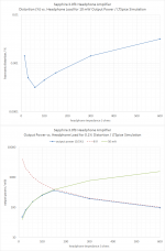
2. Performance characteristics at Rload = 600Ohm.
Basically all graphs are provided for the loads up to 300Ohm. It would be great if you could provide similar ones for 600Ohm load.
3. Removing C1 from signal path.
There is no DC offset at DAC output, so I presume I don't need the one. Shortening C1 pads would suffice? If no log volume control is used, input impedance of the amp as seen by DAC is around 47kOhm, isn't it?
4. Ground loops
To be honest, I find it hard to embrace an idea of connecting common ground to chassis ground which in turn is connected to earth. By doing so I would introduce a lot noise back to the DAC, which is pretty sensitive in that regard. Isn't the amp vulnerable to that too?
My plan is to put DAC and amp in one large chassis (so one power outlet for all devices), using plastic mounting post for all boards. The cans are slightly modded and works in balanced mode; will be connected to amps through 4-pin XLR socket. Should I connect Sapphires' common grounds together anyway? Is there anything wrong with such execution of floating ground?
Of course chassis will be connected to earth.
5. Power supply
You have stated somewhere that total power consumption of a single board is aroung 5W. Isn't 25VA trafo overkill?
6. Power regulators mods.
There are a couple of tps7a4701-based regulators at my disposal. Is there any disadvantage of using them instead of on-board z-regs? Op-amps should benefit from such a mod. It seems to me that the best way to replace on-board regulators is to remove R23, R24, R25, R26, D1, D2, Q11 and Q12. Short Q11 and Q12 pads and use standard way of powering V-- and V++ rails.
The other option is to put additional regulators between trafos and board sockets. Overall PSRR should be improved. But at the price of course.
What's your opinion?
Thanks,
[1] https://docs.google.com/spreadsheet...id=0&sortasc=true&rowsperpage=500&pli=1#gid=0
Lately I have been evaluating an idea of enriching my current setup by adding a pair of Sapphires. Since I am a newbie to DIY audio business, I would rather consult with you on several issues which apparently are not obvious to me (and maybe silly/trivial to you), before I give it a go. I hope you don't mind a lengthy post.
My plan is to put the amp between dam1021 DAC and Beyerdynamic DT 880. The basic specs of DAC: unbalanced Vout = 1.4Vrms (0V offset), Zout = 625Ohm (simply it is a voltage source); the cans as claimed by vendor: R = 600Ohm, sensivity 96dB SPL (don't know whether per mW or 1Vrms, so useless). But I found a spreadsheet [1] that claims these cans exhibit R = 619Ohm, and sensitivity around 94dB/mW. Let's stick to those. Volume control will be handled by DAC in digital domain.
1. Calculating gain.
I'm interested in getting 115 dB SPL at peaks. Using the gain calculator attached to the BOM spreadsheat I've got 33dB which differs somewhat from my calculations. According to [1] I need 10.28 Vrms, so gain = 20*log(10.28/1.4) ~= 17dB. Could you tell what 40.7-6 expression from formula at F5 cell stands for?
Occasionally I plan to use other low level impedance headphones (30-60 Ohm), so jumper gain switch will be used. But what matters the most to me is the optimal configuration for DT 880 load. Keeping this in mind: is there any difference whether R4 has low or high value? Are there any other passive components, whose values could be adjusted to such a load?
2. Performance characteristics at Rload = 600Ohm.
Basically all graphs are provided for the loads up to 300Ohm. It would be great if you could provide similar ones for 600Ohm load.
3. Removing C1 from signal path.
There is no DC offset at DAC output, so I presume I don't need the one. Shortening C1 pads would suffice? If no log volume control is used, input impedance of the amp as seen by DAC is around 47kOhm, isn't it?
4. Ground loops
To be honest, I find it hard to embrace an idea of connecting common ground to chassis ground which in turn is connected to earth. By doing so I would introduce a lot noise back to the DAC, which is pretty sensitive in that regard. Isn't the amp vulnerable to that too?
My plan is to put DAC and amp in one large chassis (so one power outlet for all devices), using plastic mounting post for all boards. The cans are slightly modded and works in balanced mode; will be connected to amps through 4-pin XLR socket. Should I connect Sapphires' common grounds together anyway? Is there anything wrong with such execution of floating ground?
Of course chassis will be connected to earth.
5. Power supply
You have stated somewhere that total power consumption of a single board is aroung 5W. Isn't 25VA trafo overkill?
6. Power regulators mods.
There are a couple of tps7a4701-based regulators at my disposal. Is there any disadvantage of using them instead of on-board z-regs? Op-amps should benefit from such a mod. It seems to me that the best way to replace on-board regulators is to remove R23, R24, R25, R26, D1, D2, Q11 and Q12. Short Q11 and Q12 pads and use standard way of powering V-- and V++ rails.
The other option is to put additional regulators between trafos and board sockets. Overall PSRR should be improved. But at the price of course.
What's your opinion?
Thanks,
[1] https://docs.google.com/spreadsheet...id=0&sortasc=true&rowsperpage=500&pli=1#gid=0
I'm happy to give advice, but many of your "questions" above sound to me more like statements of your own opinion and are therefore going to be difficult to answer without seeming combative. With that in mind, then...
1.
No you aren't. You want the right voltage gain to be able to comfortably listen to music with your headphones with the volume control around 9-11 o'clock. 600 ohms, 94 dB/mW are going to need about 30 dB of gain. For low impedance over-ear headphones, 10-15 dB is fine.
As you note, there are many different possible combinations of resistors you could use, but the idea is to keep the impedance of the feedback network (R3||R4 or R3A||R4) not too far away from 1k so as to balance the network on the noninverting input, and certainly not above 5k as that will add start to add noise into the circuit. There is a certain amount of compromise involved.
A suitable set of values for R3, R3A, and R4 is 3k3, 330 ohms, and 10 kohms, respectively.
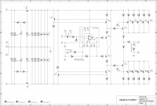
2. Sure. See attached.
3. Don't short over C1. Removing the AC coupling will mean the output offset voltage will vary with the volume position. If you spin the volume fast enough you'll be able to hear it...
4. A circuit "ground" should make a connection to the chassis once and only once. So if you have a DAC and a headphone amp sharing the box, its up to you where you want to make this connection. You have to make it though. Whether you want to connect the chassis to earth or not is up to you, but its generally a good idea. If the power supply is shared, its best to make the connection to chassis to the power supply common before the split to each channel. For dual mono both channels of course are tied to the chassis, and you have more freedom about where you want to make the connection.
5. If you think it's overkill, use a smaller one.
6. If you want to use external Vregs, use external Vregs. If you want to bridge over and disable the Zreg section, go ahead. It's not my job to convince you that the Zreg is better than whatever circuit you want to use. You are welcome to discover that for yourself. I will however suggest that there is little point putting a regulator before the Zreg. If you are going to try a different circuit, it's best to cut the Zreg out and replace it with your latest and greatest.
The Z-reg is not the best performing regulator out there, but it does its job and it does its job without feedback and without any of the problems this introduces. With no sampling, and no error amplifier, it is utterly "unfussy" about the load it is attached to. I think that's the reason it sounds as good as it does.
/R
1.
I'm interested in getting 115 dB SPL at peaks.
No you aren't. You want the right voltage gain to be able to comfortably listen to music with your headphones with the volume control around 9-11 o'clock. 600 ohms, 94 dB/mW are going to need about 30 dB of gain. For low impedance over-ear headphones, 10-15 dB is fine.
As you note, there are many different possible combinations of resistors you could use, but the idea is to keep the impedance of the feedback network (R3||R4 or R3A||R4) not too far away from 1k so as to balance the network on the noninverting input, and certainly not above 5k as that will add start to add noise into the circuit. There is a certain amount of compromise involved.
A suitable set of values for R3, R3A, and R4 is 3k3, 330 ohms, and 10 kohms, respectively.
2. Sure. See attached.
3. Don't short over C1. Removing the AC coupling will mean the output offset voltage will vary with the volume position. If you spin the volume fast enough you'll be able to hear it...
4. A circuit "ground" should make a connection to the chassis once and only once. So if you have a DAC and a headphone amp sharing the box, its up to you where you want to make this connection. You have to make it though. Whether you want to connect the chassis to earth or not is up to you, but its generally a good idea. If the power supply is shared, its best to make the connection to chassis to the power supply common before the split to each channel. For dual mono both channels of course are tied to the chassis, and you have more freedom about where you want to make the connection.
5. If you think it's overkill, use a smaller one.
6. If you want to use external Vregs, use external Vregs. If you want to bridge over and disable the Zreg section, go ahead. It's not my job to convince you that the Zreg is better than whatever circuit you want to use. You are welcome to discover that for yourself. I will however suggest that there is little point putting a regulator before the Zreg. If you are going to try a different circuit, it's best to cut the Zreg out and replace it with your latest and greatest.
The Z-reg is not the best performing regulator out there, but it does its job and it does its job without feedback and without any of the problems this introduces. With no sampling, and no error amplifier, it is utterly "unfussy" about the load it is attached to. I think that's the reason it sounds as good as it does.
/R
Attachments
I'm happy to give advice, but many of your "questions" above sound to me more like statements of your own opinion and are therefore going to be difficult to answer without seeming combative. With that in mind, then...
I think it is misunderstanding. I am not here to state my own opinions. Instead I would like to understand the reasoning behind any given design decision you've made. I'm not circuit designer nor audio specialist, but stating null hypothesis and verifying one way or another can improve my understanding.
No you aren't. You want the right voltage gain to be able to comfortably listen to music with your headphones with the volume control around 9-11 o'clock. 600 ohms, 94 dB/mW are going to need about 30 dB of gain. For low impedance over-ear headphones, 10-15 dB is fine.
Yes, I am. 110 dB SPL can be measured during philharmonic concert. 115 dB SPL is not uncommon during live rock concerts. You're right: this is not volume level I would feel comfortably with when it comes to day-to-day listening. Nonetheless on rare occasion I would like to enjoy such volume levels. What I'm interested in is the lowest gain factor that would enable me to reach those levels, given max signal levels provided by DAC with proper headphone amp characteristics.
Hmm, the "9-11 o'clock" notion is completely irrelevant here. I'm not planning to use any knob placed in signal path for volume control. I'm going to use mobile phone app as a front-end with slider for volume control on touch screeen, which is connected to music server run on single-board computer with serial connection to the DAC that would be responsible for setting volume levels. Since it is 28-bit DAC, I have plenty room for the perfect lossless stereo digital volume control (something completely unachievable in analog domain AFAIK). And the meaning of relevant slider position could defined in the application code, so this is an minor issue.
but the idea is to keep the impedance of the feedback network (R3||R4 or R3A||R4) not too far away from 1k so as to balance the network on the noninverting input, and certainly not above 5k as that will add start to add noise into the circuit.
Will keep in mind.
3. Don't short over C1. Removing the AC coupling will mean the output offset voltage will vary with the volume position. If you spin the volume fast enough you'll be able to hear it...
Either I've misunderstood schematics or I was misunderstood. If C1 pads are not wired together, there is no closed circuit between IN+ and IN-.
4. A circuit "ground" should make a connection to the chassis once and only once... You have to make it though.
But my question was: why. What's wrong with the idea of floating ground? If PCB common ground layer is properly designed, and low-impendance cable are used for connection between PCB boards there should be no problems with that, given voltage and currents levels to be seen in headphone amp. As a bonus you've got Faraday cage.
In fact that is how my current connection between dac and speaker amplifier is organized. No hum, no noise whatsoever despite the fact they are sitting 15cm away from a broadband cable router and 50cm from a wireless router.
If there is a need, then isolated busbar could introduced.
And connecting metal chassis ground to earth should be out of question.
5. If you think it's overkill, use a smaller one.
What I think doesn't matter. Is there any rational reasoning that works in favour of using 25VA-rated transformer for 5W load?
PS. Thanks for the figures.
What I think doesn't matter. Is there any rational reasoning that works in favour of using 25VA-rated transformer for 5W load
You can find reply to my question on this several posts above.
Power=E*I
You might need the power excess according to your real I here
Your power is
Power ={Diode bridge voltage consumption}*{100ma}
{Z reg Output Voltage}=16 volt
{Z reg Output Voltage}=16
So you will need at least say twice
Power = 20 volts*100ma= 2 watt
Twice 2 watt is 4 watt please note this is for zero load.
Than calculate your maximum load with maximum volume
SNR
Plus note that your snr ratio of around 100 db is for minimum volume. It would be reduced for bigger volume as well
Last edited:
Based on wiki how
Should it be around 8-10/watts than plus remeber rpund up to the nearest real value and around 2 times for the peak load
And remebe.))
Statent in english without a question sounds lile a statent, not a question. Especially in Japanese.
So to make sure you are read correctly upu can add.
" Am I right ?"
This id quite different from Polish and Russian.
English people tend to ask rather than to state.")
Make transformer size allowance for inrush current. Find the rated full load output capability of the transformer (Irfl) in amperes. The rated full output capability of a single phase transformer is determined as transformer kVA divided by Vl. The rated full load output capability of a 3 phase transformer is determined as kVA divided by (Vl time 1.732).
Should it be around 8-10/watts than plus remeber rpund up to the nearest real value and around 2 times for the peak load
And remebe.))
Statent in english without a question sounds lile a statent, not a question. Especially in Japanese.
So to make sure you are read correctly upu can add.
" Am I right ?"
This id quite different from Polish and Russian.
English people tend to ask rather than to state.
Last edited:
@aradan
Interesting. That linguistic difference would explain a lot actually.
@forta
115 dB output from 95 dB/mW headphones is 100 mW power, and for 600 ohms equal to 8 V rms. So if you want this to be obtainable at 100% volume setting from 1.4 V source the gain is 8/1.4= 15 dB.
"Either I've misunderstood schematics or I was misunderstood. If C1 pads are not wired together, there is no closed circuit between IN+ and IN-. "
I mean, you should use the capacitor C1. Do not remove the coupling capacitor from the circuit.
"What's wrong with the idea of floating ground?" "And connecting metal chassis ground to earth should be out of question."
I direct your inquiry to Horowitz and Hill, "The Art of Electronics", noting in passing that what you consider out of the question is standard industry practice.
"Is there any rational reasoning that works in favour of using 25VA-rated transformer for 5W load?"
I'm temped to say "no", remembering a similar discussion with vulejov about the Phonoclone not too long ago. Various "rules-of-thumb" exist. Mine says "2x 35VA is a nice size to use for the Sapphire amp". You understand of course the concept of peak diode currents in rectifier circuits? And that putting 10x the current through the coils in 1/10th the time generates 10x as much heat? Of course that doesn't tell you what size you *need*, but in my opinion it makes a reasonably persuasive argument in favor of over-sizing as long as the burden of cost/size does not become too great.
Last edited:
115 dB output from 95 dB/mW headphones is 100 mW power, and for 600 ohms equal to 8 V rms. So if you want this to be obtainable at 100% volume setting from 1.4 V source the gain is 8/1.4= 15 dB.
That is something similar to what I've calculated. Good news.
"Either I've misunderstood schematics or I was misunderstood. If C1 pads are not wired together, there is no closed circuit between IN+ and IN-. "
I mean, you should use the capacitor C1. Do not remove the coupling capacitor from the circuit.
Why not? The output of the DAC is DC coupled.
"What's wrong with the idea of floating ground?" "And connecting metal chassis ground to earth should be out of question."
I direct your inquiry to Horowitz and Hill, "The Art of Electronics", noting in passing that what you consider out of the question is standard industry practice.
You're right. I'm sorry: bad wording. I meant totally opposite.
So you've got: earth ground = metal chassis ground = circuit ground.
And this what you may get under such condition:
Last night I took a few measurements of my DAM. The measurements were not intended to determine the absolute performance characteristics of the DAC, but rather to determine the influence of different grounding schemes on its performance.
After I had installed a pair of alpha 20 line stages I had measured my DAM's noise floor at -87dbs, which was suspect at best.
The installation of the α20s had coincided with me changing my plastic IEC with a metal one, that also provided filtering.
Metal meant that the main's GND would be connected to my chassis. You may remember that the Soekris does not have insulation on its mounting holes, so if you are using metal standoffs to mount it you are effectively connecting your signal ground to your chassis.
To make a long story short, isolating the DAM from the chassis improved the noise floor by a whopping ~23dbs. It also made significant difference in the dynamic range, THD, etc.
or quite similar: noise coming from cable shield [1]
[1] Tracking down noise sources on a Raspberry Pi | Crazy Audio
Last edited:
Statent in english without a question sounds lile a statent, not a question. Especially in Japanese.
Yeah, that's tricky.
If you remove the coupling cap, you make a DC connection from the op amp input to the upstream circuit. The output offset voltage depends on the DC resistance seen by the op amp inputs, and - since you will not use a volume control - now this will be variable and depend on the the input impedance of the source since there is no blocking capacitor. In practice this will mean large "pops" and "thunk" sound when you plug in or unplug sources, for example.
Re grounding: yes, in certain cases where there is a problem with the grounding the circuit will be quieter when isolated from the chassis or the chassis is isolated from earth. That is the exception, however. Lifting the ground is done as a quick-n-dirty fix or when all other options are exhausted.
Re grounding: yes, in certain cases where there is a problem with the grounding the circuit will be quieter when isolated from the chassis or the chassis is isolated from earth. That is the exception, however. Lifting the ground is done as a quick-n-dirty fix or when all other options are exhausted.
If you remove the coupling cap, you make a DC connection from the op amp input to the upstream circuit. The output offset voltage depends on the DC resistance seen by the op amp inputs, and - since you will not use a volume control - now this will be variable and depend on the the input impedance of the source since there is no blocking capacitor. In practice this will mean large "pops" and "thunk" sound when you plug in or unplug sources, for example.
There is only one source. R-2R ladder with low-pass filter at the end (Zout = 625 Ohm).
Re grounding: yes, in certain cases where there is a problem with the grounding the circuit will be quieter when isolated from the chassis or the chassis is isolated from earth. That is the exception, however. Lifting the ground is done as a quick-n-dirty fix or when all other options are exhausted.
.... or states design principle. Like in case of Class II appliance. Anyway, we have drifted slightly too away, I presume.
- Home
- Amplifiers
- Headphone Systems
- RJM Audio Sapphire Desktop Headphone Amplifier