Update to rev 3.0e.
- Changed TO-92 transistors to BC327/BC337.
- Upgraded the Z-reg voltage regulator with additional RC filter, as detailed in this blog post.
- Changed TO-92 transistors to BC327/BC337.
- Upgraded the Z-reg voltage regulator with additional RC filter, as detailed in this blog post.
Attachments
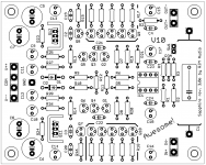
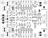
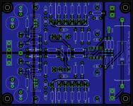
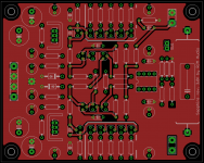
rev 3.0f [production prototype for fabrication]
As per usual, I'm going to get a small batch of these made and inviting "guinea pigs" to join in the fun. $20 for a set of two boards, including shipping. Parts (partial or full kits) available on request. Contact me if interested.
As per usual, I'm going to get a small batch of these made and inviting "guinea pigs" to join in the fun. $20 for a set of two boards, including shipping. Parts (partial or full kits) available on request. Contact me if interested.
Attachments
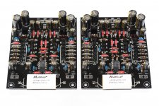
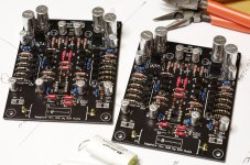
Sapphire 3.0f boards are back from the fab, assembled, and tested OK.
Assembly/test notes:
- Took me two hours of hard work to assemble. The 36 TO-92 transistors were particularly tedious.
- With both the transistors and electrolytics, my technique is to solder one lead, adjust the position (reflow if needed), then solder the remaining leads.
- Voltage drop in mV across R19,20 (1 ohm) gives the total output bias current in mA. I expect about 40 mA and got 40/40 in on board but 62/55 in the other. Took a while to track down the problem as all the voltages seemed correct. Eventually I traced the problem to R7 ... the PRP resistor was labelled 150R but measured 99.2! [Ok, that's the last time I buy PRP resistors! Geez.] I replaced the resistor (all the other ones in the bag were OK) and got 40/40 as expected. Output offset voltage is under 20 mV.
- Will put the boards in my Sapphire amp chassis tomorrow for listening trials.
(photo: Nikon D600, Tamron 90mm F2.8 Macro, Nikon SB-800 x2)
Attachments
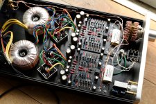
Wired up in the original chassis. (R channel input leads are shown connected backwards, an error I fixed shortly after the photo was taken.)
I did not use R3A or the gain select switch in my build, preferring to have fixed 27 dB gain with R3=1k and R4=22k.
It's breaking in at the moment.
I did not use R3A or the gain select switch in my build, preferring to have fixed 27 dB gain with R3=1k and R4=22k.
It's breaking in at the moment.
Attachments
They will all do black.
Do you know which manufacturer(s) is/are the cheapest while still producing a decent quality nongreen board?
So anyhow, an update with the Sapphire3.
First thing, the boards are stable and run perfectly cool. The bias and offset drifts are minimal. I was a bit worried about thermal drift since that's something LTSpice won't inform you about, but it seems all those emitter resistors are having their proper stabilizing influence. There is no hum or noise, even at 27 dB gain and almost nothing even with the volume at max. The sound is clean and, from a frequency response point of view, correct.
Not that I'd expect differently, it's just by way of pointing out that the circuit and board layout are, in fact, working as advertised.
If anyone want to ask me anything about the circuit and build, feel free.
Meanwhile let me comment on two questions which have come up elsewhere,
1. Why did you use 5x TO-92 transistors for the output? Why not use a single BD135/6 instead?
- it keeps the BOM simple (though in fact I ended up using BD135/136 for the regulators, this needn't be the case in general)
- it spreads the thermal load. No heatsinks are needed, and the temperature rise in any individual output transistor is about the same as the driver and input stage which helps to keep thermal drift in check.
- it averages out mismatch in current gain. If you are unlucky and pick one pnp and one npn transistor, the mismatch in hfe can be quite high. If you pick two groups of five, statistically the two average values are going to be much closer.
2. What's the point of the 1 ohm resistor R21?
It's not doing much more than acting as a 0 ohm jumper, I include it to allow for the option of replacing it with a larger value if you want. I prefer the sound with ~0 ohms, but you might want to use 10-47 ohms to linearize the gain with different headphone impedances. There's even a (dubious) case for using 120 ohms. Anyway, larger values also give a measure of overcurrent protection so its certainly a good idea to go higher if you feel the sound doesn't suffer.
Finally, the Sapphire3 is still cooking. It's coming along nicely but the electrolytics take a while to settle so it's not worth writing a review yet. I can say a couple of things though, expecially with respect to the previous version (Sapphire 2) which was a similar circuit but with no current sources:
I retrospect, the Sapphire 2 has a slight distortion in the treble. It manifests as low level grunge which I admit I rather liked since it generally gave the sound a raw, powerful edge. The grittiness obscured some of the treble detail which helped to subjectively focus the stereo image more centrally and emphasize the more percussive elements of the bass and lower midrange. Within the context of headphone listening and headphone amps generally I'd allow this as "character" or "shading".
The Sapphire 3 doesn't have that trait. It's smooth and detailed. Still powerful, but more polite. The soundfield is especially impressive, nicely 3D/immersive. I'm expecting the bass to open out a bit in the next few days as the caps break in, ditto I expect the treble to refine as the coupling cap C1 settles.
Anyhow, I'm liking this a lot.
Well, what quantities are you looking at?
Twenty five boards or less.
25 pcs is about the cutoff, much less and you are better going with hobbiest or prototype shops, while once you get up around 40-50 pcs, usually, the regular places will give you a better deal.
If you can handle sending in Gerber files a don't mind a $50~60 tooling fee you might give pcbcart a try, its where I go but I suspect they will be a little expensive for the quantities you have in mind.
If you can handle sending in Gerber files a don't mind a $50~60 tooling fee you might give pcbcart a try, its where I go but I suspect they will be a little expensive for the quantities you have in mind.
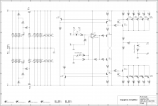
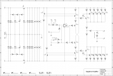
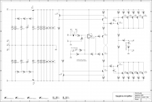
Sapphire 3.0f2 BOM
Sapphire 3.0f provisional BOM and Eagle files, and the "final" schematic (3.0f2). The final number (f, f1, f2) indicates an adjustment in parts values only, with no layout or circuit changes.
Sapphire 3.0f provisional BOM and Eagle files, and the "final" schematic (3.0f2). The final number (f, f1, f2) indicates an adjustment in parts values only, with no layout or circuit changes.
Attachments
An update. Where I've been these last few weeks.
1. Break-in hell. The electrolytics take about a week powered up to fully settle. That's not a big deal, just leave the amp powered up. The coupling cap, on the other hand, only sees the signal voltage. That means it times by playback hours rather than hours powered. I should have hooked the Multicaps up on the AC line for a few days before using them but I didn't, I suppose I could have connected the Sapphire amp to a CD player running on repeat but I don't have a CD player or anything else really convenient for the purpose. So anyway, it was taking forever and was driving me nuts so I ended up pulling the caps out of the boards and replacing them with a set of Mundorf Supreme EX which had been broken in previously.
2. The change in caps brought in a welcome warmth and smoothness. (In comparson the Multicaps are more transparent, but have a tendency - decreasing as they break in - to "flare up" on transients. Anyhow, with the coupling caps sorted I could focus my attention on a remaining annoyance: a slight channel asymmetry. Basically the left channel sounded brighter than the right, which pulled the stereo image off center even though the measured frequency response showed that the actual level imbalance was just 0.07 dB. [The Gustard H10 which I'm using as a comparative reference at the moment clocks 0.25 dB left, yet sounds properly centered.] The left channel also ran at about 15% higher bias current, and was noisier when the volume was turned up to max. Other than the higher current in the output transistors x5 banks, however, there was no other voltage/current/resistance that seemed out of order compared to the other channel. The issue is at any rate extremely slight.
So this has me kinda stumped at the moment. My operating theory is one of the transistors (most likely one of Q1,2,7,8) is not functioning 100%, though its possible it's within spec but just a real outlier on the hfe distribution curve. (I didn't try to match the transistors.) I figure pulling out and replacing transistors until (if/when) I hit on the problem device is not a viable strategy for reasons of maintaining my sanity, instead I will make myself another set of boards paying attention to matching all the values and see what happens.
Last edited:
I know removing to-92 is tough and then getting new ones in their is even more challenging. ..but if you have a good solder sucker, lead snips and flux its not too bad. Snip the head off if to-92 then hold lead with pliers, heat and remove. Add flux near through hole, heat and suck solder.
Atlas sells a transistor tester that also has a curve trace function for around $130. It talks to a computer as well. Super simple to use.
Atlas sells a transistor tester that also has a curve trace function for around $130. It talks to a computer as well. Super simple to use.
Second set of boards are finished. Things went much more smoothly this time. I checked all the resistors before assembly, and measured the Hfe of all the transistors. I even matched the Zeners.
It was not possible to match the BC337 and BC327 transistors due to the overly tight binning: 90% of the BC337 were between 220-240, and 90% of the BC227 were between 270-290. At least though I could screen the devices, discarding the outliers. That leaves the inherent symmetry of the buffer circuit free to mop up the imbalance.
Clean off flux, leave to dry overnight. Testing tomorrow.
Attachments
- Home
- Amplifiers
- Headphone Systems
- RJM Audio Sapphire Desktop Headphone Amplifier