The project is now in beta. This means I could in principle send the boards out for production now with good results. I'm going to sit on it for a bit though in case anything comes up - something usually does.
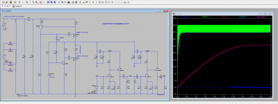
Here is the LTSpice simulation, updated to the latest board revision.
Turn on in 3 seconds. Turn off in around 1 second. Turn off "thump" fairly large (-6 V peak) and unavoidable, so you want to turn down the volume before powering off the circuit. Voltages on all transistor devices during turn on and turn off within safe margin.
Output power supply noise <120 dB at 120 Hz. As per the discussion above this is fine. This is before the "turbo mode" of shorting over R24 is engaged. This is my "in case of emergency break glass" feature built into the power supply. It is designed to operate at 20 dB de-rated performance in the interests of stability. If you want to do that Mad Max thing where they spit gasoline into the carburetor, you have the option with this circuit!!
RIAA response is very accurate. <0.5 dB 20-20k Hz. Midband gain is 37 dB.
Power draw is minimal. One channel draws just 17 mA / 0.5 W. Keeping the current low means the capacitance works very efficiently at reducing ripple.
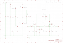
Attachments
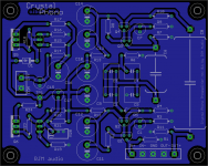
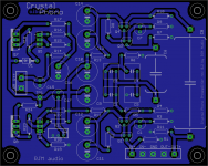
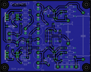
Here is the rev 0.1 board, with the Eagle schematic.
TP1 is the test point used when adjusting the trim pot R20 to set the output voltage to 25 V.
Although connectivity is complete with just the bottom layer trace, the board has a top ground plane as well to improve shielding and lower the ground impedance. (It is not shown in pic below for clarity.)
TP1 is the test point used when adjusting the trim pot R20 to set the output voltage to 25 V.
Although connectivity is complete with just the bottom layer trace, the board has a top ground plane as well to improve shielding and lower the ground impedance. (It is not shown in pic below for clarity.)
Attachments
Beta 0.2
Power supply transistors T1,2 changed to TO-126 BD135,6 and renamed Q5,6. Some resistors renamed and re-positioned.
The BD135,6 transistors are readily available in higher voltages, the ECB pinout simplifies the layout a little, and the parts are in my cross-project BOM i.e. parts I keep in stock for all kinds of purposes.
Electronically there is no change in circuit performance.
Attachments
Last edited:
The jFETs are going to be a pain point.
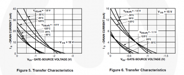
2N5484 are no longer stocked at Mouser. 2N5457 is apparently a valid substitute and is stocked, but I don't have spice models for it.
Even if I did, it's hard to know if what LTSpice shows as the behavior will be the behavior of the device that shows up at the door. This is the case as much for the 2N5484 as the 2N5457, both because the parameter variation between any two devices of the same type is large, and because there is little guarantee that the models themselves are especially close to the average value of the real device.
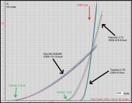
Case in point, the Idss (Vgs=0 V, Vds=15 V) of a 2N5484 in LTSpice "measures" 6.7 mA, when according to the Fairchild datasheet Idss should be between 1 and 5 mA.
So according to LTSpice the match to the 2N5484 is the 2N5458, but datasheet-to-datasheet the match is the 2N5457.
The only way forward is to order samples of the more promising devices and measure a few to check.
2N5484 are no longer stocked at Mouser. 2N5457 is apparently a valid substitute and is stocked, but I don't have spice models for it.
Even if I did, it's hard to know if what LTSpice shows as the behavior will be the behavior of the device that shows up at the door. This is the case as much for the 2N5484 as the 2N5457, both because the parameter variation between any two devices of the same type is large, and because there is little guarantee that the models themselves are especially close to the average value of the real device.
Case in point, the Idss (Vgs=0 V, Vds=15 V) of a 2N5484 in LTSpice "measures" 6.7 mA, when according to the Fairchild datasheet Idss should be between 1 and 5 mA.
So according to LTSpice the match to the 2N5484 is the 2N5458, but datasheet-to-datasheet the match is the 2N5457.
The only way forward is to order samples of the more promising devices and measure a few to check.
I think the LTSpice models for the 2N548x series are wrong. The Idss values are messed up, with the Idss of the 5484, 6.7 mA, is the value that should have been used for the 5485, and so on.
For other models, like the 4416, the Idss in LTSpice (10 mA) lines up correctly in the middle between the min and max datasheet values (5 and 15 mA).
Hard to tell from the parameters since Idss isn't given explicitly. Seems that the Beta value is the problem. Note the data set of the 2N548x seems to be more rudimentary than that of the 2N4416...
*****
.model 2N5484 NJF(Is=.25p Alpha=1e-4 Vk= 80 Vto=-1.5 Vtotc=-3m Beta=3.0m Lambda=10m Betatce=-.5 Rd=10 Rs=10 Cgs=4p Cgd=4p Kf=3e-17 mfg=Siliconix)
.model 2N5485 NJF(Is=.25p Alpha=1e-4 Vk= 80 Vto=-2.0 Vtotc=-3m Beta=3.5m Lambda=10m Betatce=-.5 Rd=10 Rs=10 Cgs=4p Cgd=4p Kf=3e-17 mfg=Siliconix)
.model 2N5486 NJF(Is=.25p Alpha=1e-4 Vk= 80 Vto=-4.0 Vtotc=-3m Beta=4.0m Lambda=10m Betatce=-.5 Rd=10 Rs=10 Cgs=4p Cgd=4p Kf=3e-17 mfg=Siliconix)
.model 2N4416 NJF(Beta=989.4u Betatce=-.5 Rd=1 Rs=1 Lambda=5.5m Vto=-3.06 Vtotc=-2.5m Is=33.57f Isr=322.4f N=1 Nr=2 Xti=3 Alpha=311.7u Vk=243.6 Cgd=1.6p M=.3622 Pb=1 Fc=.5 Cgs=2.414p Kf=7.445E-18 Af=1 mfg=Fairchild)
*****
Last edited:
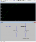
Editing the beta as follows gets results much closer to the datasheet Idss values:
.model 2N5484_RJM NJF(Is=.25p Alpha=1e-4 Vk= 80 Vto=-1.5 Vtotc=-3m Beta=1.25m Lambda=10m Betatce=-.5 Rd=10 Rs=10 Cgs=4p Cgd=4p Kf=3e-17 mfg=Siliconix)
.model 2N5485_RJM NJF(Is=.25p Alpha=1e-4 Vk= 80 Vto=-2.0 Vtotc=-3m Beta=1.75m Lambda=10m Betatce=-.5 Rd=10 Rs=10 Cgs=4p Cgd=4p Kf=3e-17 mfg=Siliconix)
.model 2N5486_RJM NJF(Is=.25p Alpha=1e-4 Vk= 80 Vto=-2.5 Vtotc=-3m Beta=2.25m Lambda=10m Betatce=-.5 Rd=10 Rs=10 Cgs=4p Cgd=4p Kf=3e-17 mfg=Siliconix)
Attachments
OK, I think we are back in the game with jfets.
What we are looking for is saturation drain current (Idss) around 3-4 mA. Then, the working bias current can be safely set to 2 mA, giving the correct voltage drop through the 6.8k drain resistors R2,8. 2N5484 will work fine, 2N5457 should be ideal. Higher current bins like the 2N5485 and 2N5458 can be made to work by adjusting the value of the resistors, though the gain will be reduced a little. 2SK170 is an oddball, but will also work after changing source resistors and removing the source bypass caps, though the high circuit gain is suitable for MC carts only.
So even though it is not stocked at Mouser, 2N5457/2N5484 are both common and cheap on eBay making either a safe choice for the present.
Last edited:
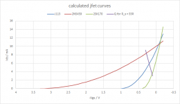
JFETs are, for our purposes here, completely defined by two parameters I_dss and V_gs0, saturation current and pinch-off voltage respectively.
If we also specify the power supply voltage, and one other parameter, the drain voltage, all the circuit values for the JFET amplifier stage fall into place.
As a rough guide (I'll spare you the derivation) the relationships are as follows,
For I_dss in mA and V_gs0 in volts,
R2,8 (R_drain, drain resistor, in kohms) 25 / I_dss
R3,9 (R_source, source resistor, in ohms) 270 * V_gs0 / I_dss
R4,10 (R_follower, source resistor of the follower stage, in kohms) 12 / I_dss
C1,7 (C_source, source bypass capacitor, in uF) 50000 / R_source
In this way inevitable variations in the device parameters (I_dss from 2 to 8 mA approx.) can be accommodated by adjusting the circuit values. So, if you can find a nice matched quad of 1.7 mA 2N5457, then you make the necessary changes. The numbers are not meant to be exact, so use close convenient values.
Tutorial on jfets attached. (not mine, but I forget where I got it.)
Attachments
Last edited:
Why does it have to be the low gain 2N5457, 2N5484 or the expensive LSK170 ???
I think there are very nice Jfets out there that are both available, inexpensive, AND are high transconductence higher voltage and low noise at the same time.
For example the J113 or the PF5102...
I think there are very nice Jfets out there that are both available, inexpensive, AND are high transconductence higher voltage and low noise at the same time.
For example the J113 or the PF5102...
Last edited:
It doesn't! My grasp of JFET selection is just not so extensive that those came to mind. (I have no idea why the J113 didn't show up when I searched Mouser for stocked JFETs earlier.)
Those JEFTs are marketed as switches rather than linear amplification which is a bit worrisome, but so far as the Idss/Vgs0 parameters go they looks very good.
So the list of "probably okay" JFETs now extends to:
J112/3
2N5457/8
2N5484/5
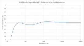
The circuit design point (aka ideal part) is Idss 3-4 mA and Vgs0 1.5-2 V. The "beta" Idss/(Vgs0^2) should be at least 0.0013.
Those JEFTs are marketed as switches rather than linear amplification which is a bit worrisome, but so far as the Idss/Vgs0 parameters go they looks very good.
So the list of "probably okay" JFETs now extends to:
J112/3
2N5457/8
2N5484/5
The circuit design point (aka ideal part) is Idss 3-4 mA and Vgs0 1.5-2 V. The "beta" Idss/(Vgs0^2) should be at least 0.0013.
Last edited:
List of JFETs extended to include the J202 (seems a very good choice, and I happen to have some already), but I'll remove the larger models as it's unlikely many useful devices can be harvested,
J202
J113
2N5457
2N5484
The design center values are I_dss 3 mA and Vgs0 = 1.5 V. Maximum allowable before things go south is I_dss 4 mA and Vgs0 = 2 V. It's not possible to crank out enough gain from the circuit with larger values.
I've just published a blog post about how I propose to go about matching jfets
http://www.diyaudio.com/forums/blogs/rjm/1326-matching-jfets.html
Thanks, that's super-helpful.
While it's generally what I had been lead to expect, I hadn't realized the transconductance of the J113 so much higher than the other parts on my list. That's encouraging, your data shows the J113 can generate enough gain that the source does not need to be bypassed to hit the target 35 dB circuit gain. (This is useful since the feedback acts to reduce the gain variation between devices.)
A reasonable set of resistance values for those J113s would be,
Rd 3k3
Rs 33R
Cs (no bypass cap)
Rfollower 1~2 k
operating the stage at Vgs -200 mV and Ids 6 mA.
Taking another look at my datasheets, the J202, 2N5484, and even the 2N5457 should work - with bypassed source resistors for "typical" values, and without if unusually low V_gs0 and high g_m parts can be matched.
The trick with all of these is harvesting enough parts with V_gs0 1.0~2.0 V to find two closely matched pairs in that range.
Attachments
Last edited:
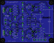
rev 1.1a
The JFET packages I used were not the correct pinouts. J202, J113, 2N5457 and 5484 are all TO-92 1D 2S 3G ie. DSG. The earlier package I used was a 2N3819 which is DGS.
The TO-92 outline has been rotated to match the correct pinout. Trace isolation reduced from 032 to 024 mils.
The JFET packages I used were not the correct pinouts. J202, J113, 2N5457 and 5484 are all TO-92 1D 2S 3G ie. DSG. The earlier package I used was a 2N3819 which is DGS.
The TO-92 outline has been rotated to match the correct pinout. Trace isolation reduced from 032 to 024 mils.
Attachments
rev. 1.1a are "RTM" (release to manufacturing) I should have the boards back in a couple of weeks.
meanwhile, the BOM in its current state is attached.
<sigh>
Whoever had the idea of using jfets for open loop amplification in stereo audio should have their heads examined. It's like herding cats. It's normally understood that JFET transconductance will vary from device to device, so they are used with plenty of feedback to level out the voltage gain.
With this circuit, we must rely on the jfets themselves to provide accurate channel gain balance. As I said: its like herding cats.
Attachments
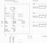
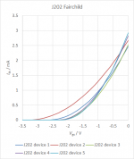
I tested some J202 fets using the two point method.
All five jfets were close the the center of the range given by the datasheet.
Average V_gs0 2.6 V (datasheet range 0.8-4 V)
Average I_dss 2.7 mA (datasheet range 0.9-4.5 mA)
With an average beta value of 0.0004 A/V^2, and pinch-off voltages well above 2 V, these devices are not suitable for use in the CrystalFET circuit.
Attachments
Last edited:
This circuit is so pure, one of the best ever - do not use a pcb! Glue the transistors at a alu-board and set the pieces on. You will prevent a lot of unnecessary soldings, unnecessary circuits, unnecessary resonances of pcb and other materials and more. The sound will be more clean, more fine, more dynamic,-!
- Status
- This old topic is closed. If you want to reopen this topic, contact a moderator using the "Report Post" button.
- Home
- Source & Line
- Analogue Source
- RJM Audio Crystal P jfet phono preamplifier | development thread