Hey, what about this? I hear alot but not enough about the 6s45p tubes. How do they perform as small signal? Or should I just keep it to the small preamp triode category (like 12ax7). What about pentodes with alot of gain?
What about taking a respectable phono preamp and leaving out the RIAA?
PhonoDude PCB Version
DIY ECC802S (12AU7 / ECC82) Vacuum Tube SRPP Preamplifier
Need more gain! (im ok with transformers)
Im curious to see the options but im having a hard time narrowing down the playing field.
What about taking a respectable phono preamp and leaving out the RIAA?
PhonoDude PCB Version
DIY ECC802S (12AU7 / ECC82) Vacuum Tube SRPP Preamplifier
Need more gain! (im ok with transformers)
Im curious to see the options but im having a hard time narrowing down the playing field.
Attachments
Oh ya, Spice for sure. It looks like he had in his test graphs down below that it appears to have 51.3db of gain. So if I put a 1:10 transformer in front that should be another 20db of gain? 70!?
What about the SRPP Preamp link? How does it compare, (pro/con).
And how does these small signal tube designs put up with something more exotic (like a single stage small signal pentode)? Nowhere as linear?
What about the SRPP Preamp link? How does it compare, (pro/con).
And how does these small signal tube designs put up with something more exotic (like a single stage small signal pentode)? Nowhere as linear?
I got an issue here.
LTSPICE requires inductance and serial resistance for transformers.
But no transformer producer publish inductance. I've checked Lundahl, Jensen, Sowter and Samar. Nobody publishes inductance by some reason.
This makes simulations kind of guesswork.
Marik, if you are here, could you please tell me inductance (of each coil) of your transformers:
Mic xformers RT36 RT40;
Input one, something about 1:5 and 1:10, I cannot find those on your web page;
Output ones CT5 CT10.
Or someone advise me how to derive inductance from, let say, linear resistance and ratio.
Or if you know approximate figures please share.
Last edited:
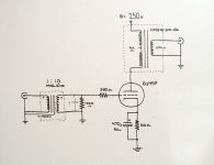
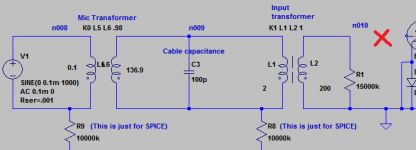
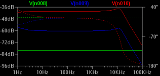
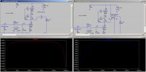
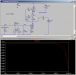
Weird issue. Phase suddenly changes at 1kHz and then level drops down if circuit is connected to grid of tube U1. The impact is propagated back to node n009. (first and second pictures)
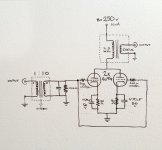
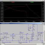
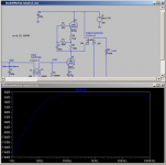
However if I cut grid wire, the phase change shifts beyond 10kHz and is not that bad till 20kHz. (second and third pictures)
This effect has appeared when I've added Mic with Mic transformer K0 and cable cap to the circuit.
FRC was flat far beyond 30kHz before this introduction of Mic and cable.
Playing with cable capacitance and inductances of mic and input xfrmrs does not improve the thing. Tube models are from Koren_Tubes.inc
I feel something is wrong here.
Where I am wrong?
LTSpice file DudeRMxFmr1stg.asc is attached if you wish to try it.
Attachments
Weird issue. Phase suddenly changes at 1kHz and then level drops down if circuit is connected to grid of tube U1...
This effect has appeared when I've added Mic with Mic transformer K0 and cable cap to the circuit...
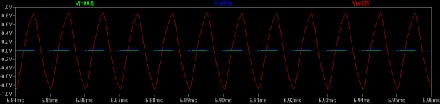
Fixed! Issue was I named Mic Xformr K0. It looks like LTSpice does not like this. I've renamed it to K3 and everything looks perfect now.
The amp produces output voltage amplitude -2V to +2V from -+3.5 mV of input, it is 55dB.
Do I need to add second stage?
Hey mm7, Thankyou for spending the time producing simulations!
I was going to mention that the guy used a 5755 tube in the first stage because of its ability to have a zero volt bias? Or is this just a waste of time... & / or how would you simulate that. I could only assume that the ECC83 tube is plenty fine enough.
What would the dB gain be like with capacitors instead of transformers?
I do not know. the simulation works well without a cathode resistor. I tried LED there but did not see any effect of it.
I am not that knowledgeable to explain why.
I do not think you can use it without input TF.
Otherwise gain will be too little.
Output TF is 1:1 and can be replaced with a capacitor. Gain will be same.
Sound may be not.
Above I've attached LTSpice circuit you can play yourself. LTSpice is free.
I am not that knowledgeable to explain why.
I do not think you can use it without input TF.
Otherwise gain will be too little.
Output TF is 1:1 and can be replaced with a capacitor. Gain will be same.
Sound may be not.
Above I've attached LTSpice circuit you can play yourself. LTSpice is free.
Hey mm7,
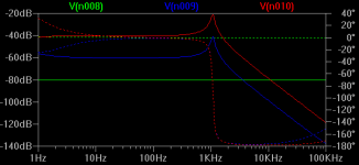
I think I ran into the problem you apparently figured out in LTspice. I tried renaming the directive to say K3 as opposed to K0. And there appears to be no change in the simulation? I just get that surreal phase shift. Also what is that resonance peak at 1k? When I slap some capacitors in there instead, I get a more meaningful arrangement.
I think I ran into the problem you apparently figured out in LTspice. I tried renaming the directive to say K3 as opposed to K0. And there appears to be no change in the simulation? I just get that surreal phase shift. Also what is that resonance peak at 1k? When I slap some capacitors in there instead, I get a more meaningful arrangement.
Attachments
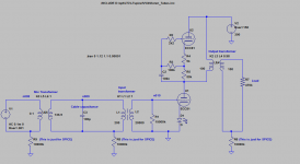
I've moved output transformer to anode. This way it has even better gain.
Experts, please comment on this schematics.
I am not sure about role of cathode LED. I saw it on web somewhere. Simulations are same with and without it.
woodrough,
Regarding your question about transformerless variant - I think it will be unsafe to have capacitor (no transformer) on output, because voltage there is about 300V. I believe that transformer isolates better.
Attachments
Hey mm7,
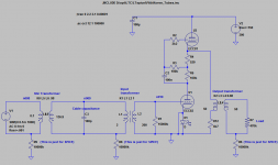
This is awesome! Its working now, and its pretty fun to play and compare things. First things off, I put a transformer output layout next to a output capacitor layout.
The gain on the 1:1 transformer appears to be slightly higher by 0.5dB on the flat spots compared to the capacitor.
At 5uF to 10uF, the base response becomes just about flat. With the transformer, if you increase the coupling efficiency number, the high end will get more and more flat.
Perhaps interesting! Wouldn't it be interesting if there is a way to take/hybridize from both worlds to get an insane flat response curve?
Also, how would you set up a THD test? I kinda want to compare between anode and cathode connected setup (before design). As well as THD difference between transformer and capacitors.
Its probably not the greatest thing to have such a flat curve... probably pick up useless sounds.
-Kyle Dell'Aquila
Attachments
Wouldn't it be interesting if there is a way to take/hybridize from both worlds to get an insane flat response curve?
Also, how would you set up a THD test? I kinda want to compare between anode and cathode connected setup (before design). As well as THD difference between transformer and capacitors.
Its probably not the greatest thing to have such a flat curve... probably pick up useless sounds.
-Kyle Dell'Aquila
From practical perspective I would not care if curve starts drop before 10Hz and after 20KHz. I do not think you can detect any sonical difference of this superflat FRC.
THD is a next task for me.
What concerns me is distortion of shape of square signal in transient simulation.
Why experts are keeping silence?

- Status
- This old topic is closed. If you want to reopen this topic, contact a moderator using the "Report Post" button.
- Home
- Amplifiers
- Tubes / Valves
- Ribbon Microphone Preamp