Hi,
I'd be interested to see the results of a set of //ed 6C45s + a CCS/mu-follower.
The fact that paralleling them increases Cg-in actually helps reduce the 6C45s tendency to oscillate.
In practice it's not going to be easy since these are single triodes with a lot of pin connections to take care of.
Could it be that TINA assumed a lead acid battery?
Even if they turn out to be non-linear which is of course entirely possible, it does not even matter here since the discharge current is way too low to have any effect.
Ciao,")
So far 2 paralleled 6S45P-E passive load stage shows best result.
I'd be interested to see the results of a set of //ed 6C45s + a CCS/mu-follower.
The fact that paralleling them increases Cg-in actually helps reduce the 6C45s tendency to oscillate.
In practice it's not going to be easy since these are single triodes with a lot of pin connections to take care of.
If you use battery bias, you must bypass it with a large capacitor
Could it be that TINA assumed a lead acid battery?
Even if they turn out to be non-linear which is of course entirely possible, it does not even matter here since the discharge current is way too low to have any effect.
Ciao,
Could it be that TINA assumed a lead acid battery?
Even if they turn out to be non-linear which is of course entirely possible, it does not even matter here since the discharge current is way too low to have any effect.
Ciao,
NO. A simple search of the existing literature will show you conclusively that all battery chemistries have a non-linear impedance with frequency. Yes, it does matter because the AC ground for the transformer secondary will not be constant with frequency. This will cause distortion. I'm not sure why I bother answering these questions.
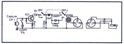
Here is another variant, where in accordance with Merlin Blencowe conclusion "For minimum noise the input stage should be passively loaded."
I've made input stage passively loaded. As well as paralleled for higher Gm.
Here are schematics of the input stage.
One is traditional with bypassed Rk.
Another is with battery bias.
Noise and transient simulation is identical for both.
Which one do you like more?
If you parallel vacuum tubes or any other active device, you cannot assume that they will share current equally. In order to do this successfully, and practically, you must treat each device as an individual.
Data? I haven't tested batteries, but I've certainly tested LEDs, and they don't have any significant change in their impedance up to 85kHz (my measurement limit).
My mistake. They are fine up to about 100 kHz.
Hi,
Maybe because you insist on bringing solutions to problems that are long solved or do not require solving?
In theory.
Ciao,
I'm not sure why I bother answering these questions.
Maybe because you insist on bringing solutions to problems that are long solved or do not require solving?
If you parallel vacuum tubes or any other active device, you cannot assume that they will share current equally. In order to do this successfully, and practically, you must treat each device as an individual.
In theory.
Ciao,
NO. A simple search of the existing literature will show you conclusively that all battery chemistries have a non-linear impedance with frequency. Yes, it does matter because the AC ground for the transformer secondary will not be constant with frequency. This will cause distortion. I'm not sure why I bother answering these questions.
I agree the impedance vs frequency is chemistry dependent but most of the extracted models use only linear R's and C's hence no distortion per se. Nakamichi used this battery self bias scheme with great success, it's interesting to note it used a mercury battery and now folks have to hunt down a fairly obscure alkaline eqivalent. Never thought of trying to measure the distortion. In any case I would expect it to be a small fraction of the base ESR, 2.9 Ohms for a 9V alkaline at 1kHz.
Attachments
I agree the impedance vs frequency is chemistry dependent but most of the extracted models use only linear R's and C's hence no distortion per se. Nakamichi used this battery self bias scheme with great success, it's interesting to note it used a mercury battery and now folks have to hunt down a fairly obscure alkaline equivalent. Never thought of trying to measure the distortion. In any case I would expect it to be a small fraction of the base ESR, 2.9 Ohms for a 9V alkaline at 1kHz.
So, your logical attack on what I said is that if it's good enough for Nakamichi, it's good enough for us? Your "appeal to authority" argument is a well known fallacy.
I didn't say anything about measuring distortion of a battery. I said: the impedance of a battery is nonlinear with frequency. It is a well known phenomena in the Electrochemical Impedance Spectroscopy field.
Wow! Excuse me.
Wow! Excuse me.
I'm sorry, you seemed to be saying something that apparently wasn't there.
Maybe because you insist on bringing solutions to problems that are long solved or do not require solving?
and you have all the solutions to all the problems and no improvements can ever be made, or what? Would you tell that to the OP then? "Your design is crap and don't bother designing a ribbon microphone preamp because it's already been done and nothing you can do will ever improve on them." That's basically what you appear to be saying. That doesn't sound very polite or even very helpful of you now does it?

I said: the impedance of a battery is nonlinear with frequency. It is a well known phenomena in the Electrochemical Impedance Spectroscopy field.
It's all very well stating a fact, but it's of no use to anyone unless you make some attempt to quantify it. Heck, everything varies with frequency if you get down to small enough numbers. And if it's so 'well known', then it should be easy to put some numbers on it.
In this example, a PP3 varies its impedance by less than 30 ohms in the audio band. Other batteries even less. That's negligible compared with the total loading on the transformer.
http://www.omicron-lab.com/fileadmin/assets/application_notes/App_Note_Battery_Impedance_V1_0.pdf
Target is to build best possible tube preamp for a ribbon mic to use in (my home) studio. For this it requires to experiment with various preamp design topologies and various tubes.Sorry to butt in so late in the thread, but is the purpose to design and experiement with preamp design toplogies/various tubes or having a working preamp for use in the studio?
Good question. Currently nothing. Otherwords it is benchmarked against itself . As soon as I reach top performance, I probably will compare it with others.
I would say currently target is flat frequency response in 20-20kHz -3dB at ends. Low THD, >0.1% or so, and low noise. Noise signal should be -115dB down to 200Hz, from 200Hz it may be < -100Db.
Yes I realize that contemporary SS are muuuuch better.
. As soon as I reach top performance, I probably will compare it with others. I would say currently target is flat frequency response in 20-20kHz -3dB at ends. Low THD, >0.1% or so, and low noise. Noise signal should be -115dB down to 200Hz, from 200Hz it may be < -100Db.
Yes I realize that contemporary SS are muuuuch better.
MM7
you will never get the -115dB s/n with tubes; if you have a right test set , with B filtering, you can reach 100 dB
But with a very good power supply also down from 200Hz the results can be interesting.
(of course if all cabling and screen for interference are made fine).
Bye
Walter
you will never get the -115dB s/n with tubes; if you have a right test set , with B filtering, you can reach 100 dB
But with a very good power supply also down from 200Hz the results can be interesting.
(of course if all cabling and screen for interference are made fine).
Bye
Walter
Hi,
Agreed.
One good place to start is to increase the efficiency of the mic itself by using thinner alu foil, a higher ratio SUT and ditto SUT at the input of the pre.
Once you have a signal level of say 0.5mV you can then optimize the circuit.
I realize I said this before but I really don't see any other way.
Ciao,
you will never get the -115dB s/n with tubes; if you have a right test set , with B filtering, you can reach 100 dB
Agreed.
One good place to start is to increase the efficiency of the mic itself by using thinner alu foil, a higher ratio SUT and ditto SUT at the input of the pre.
Once you have a signal level of say 0.5mV you can then optimize the circuit.
I realize I said this before but I really don't see any other way.
Ciao,
It is not really SNR. It is what signal a preamp shows with 150R in input XLR.
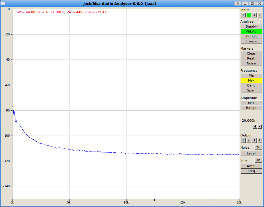
Here is full pic http://www.diyaudio.com/forums/tubes-valves/234937-ribbon-microphone-preamp-60.html#post3882955
I am happy with it after 5K, and would like just to reduce flicker noise.
But I suspect 6S45P has increased flicker noise because was designed for RF not AF. Or it is I am unlucky to get these noisier ones. That is why I asked if EF86 (6J52P) is quiter.
Last edited:
- Status
- This old topic is closed. If you want to reopen this topic, contact a moderator using the "Report Post" button.
- Home
- Amplifiers
- Tubes / Valves
- Ribbon Microphone Preamp