In his presentation at the 2013 Burning Amp get-together, Nelson Pass introduced a simple (4 active devices) symmetric complementary folded cascode preamp circuit using the Linear Systems LSK170 and LSJ74. Those who want to view the original circuit can scoot over to the Pass forum where there are a couple of threads. If someone wants to post a picture of the original circuit here in this thread, that's fine with me.
Anyway, I never leave anything alone, so I adapted the original circuit to use cheap and available J113 and J176, still available either new or as not-very-hard-to-find NOS. I added current sources to increase the supply rejection - the original circuit used resistors.
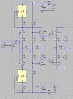
Attached is a preliminary circuit RIAA preamp circuit that cascades 2 of the gain cells (one with an added output follower), and uses passive equalization. This circuit can also be adapted to use the original Linear Systems/Toshiba parts (maybe worthwhile for the input stage, though I like the low capacitance of the J113 and J176). At any rate, food for thought. When I get the chance, I'll add a 6X gain line amp circuit.
Anyway, I never leave anything alone, so I adapted the original circuit to use cheap and available J113 and J176, still available either new or as not-very-hard-to-find NOS. I added current sources to increase the supply rejection - the original circuit used resistors.
Attached is a preliminary circuit RIAA preamp circuit that cascades 2 of the gain cells (one with an added output follower), and uses passive equalization. This circuit can also be adapted to use the original Linear Systems/Toshiba parts (maybe worthwhile for the input stage, though I like the low capacitance of the J113 and J176). At any rate, food for thought. When I get the chance, I'll add a 6X gain line amp circuit.
Attachments
I'm starting to lay this thing out - I may change the first compensation capacitor to 330nF instead of 320. I have a lage pile of BC metallized polypropylene caps. If I can select a couple that are 320 nF (3% low) I may go that route, or just find a couple that are spot on at 330nF and alter my compensation values accordingly.
The preamp is sitting on my kitchen table, waiting for me to match up all the jfet pairs to populate it. I found a bag of fairly ancient J176s (either Intersil or Interfet), and I'll try to pair them up with some NOS Siliconix J113s I have readily at hand. I've been spending most of my spare time trying to finish up my "Vanilla" power amp - maybe everything will gel over the long weekend.
Since the first RIAA stage is a folded cascode and I'm working against the load resistor, the cap values will be relatively large, depending also on the output impedance of the cascode transistors. The values shown in the first schematic are wrong. I have the right ones loaded into my first board, and will post a corrected schematic when I get a chance
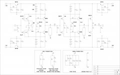
Here is the schematic I'll be dealing with to start with. The RIAA values have been corrected. The cascode devices on the first stage have been replaced with mosfets instead of bipolar transistors, as the much higher output impedance of the mosfet cascodes will result in less RIAA error for values assuming a pure current source output for the first RIAA gain stage. You could always drive the finished preamp with a reverse RIAA network and trim out the error introduced by the very finite impedance of bipolar cascodes, but I chose not to do that. The line amp circuit will follow when I get some jfets selected and get all the biasing resistors sussed out.
Attachments
I took some time to try and match up some pairs of J113 and J176 during the long Thanksgiving weekend. The stocks of J176 I had on hand were relatively hot (read high Idss/cutoff voltage), and a poor match for the J113s I had available. I had much better luck finally using PN4393s instead of the J113s, and was able to get 10 closely matched pairs, though it still was a thundering pain in the rear. I'm beginning to see why I've been using single ended circuits for so long... The single ended folded cascode gain cells I've simulated are a lot simpler, and simulated THD and harmonic distribution are fairly comparable to the symmetric circuits. I'll probably take this project to completion, but my enthusiasm for it wanes as I trudge forward.
At any rate, I changed my matching parameters, and will be running 5ma or so quiescent current in the jfets instead of the 3ma originally planned. This will change some resistor values, and I'll post a revised schematic when things settle down.
Edit - another possibility (besides the original LSK parts) might be the 2SJ107 and 2SK246 - since these are Japanese parts they are available in IDSS rankings that should make matching a lot simpler, unlike the parts I'm currently trying to use, which can be all over the place.
Last edited:
Per a conversation with Juma in his thread on his version of this preamp, I may try matching up some J175s and PN4393s at 10ma drain current for lower distortion and noise. The noise goes down somewhat with higher drain current, and the required source resistor values go down as well. The overall distortion will also go down with a higher standing current in the gain stage. I may also have better luck finding matched pairs at the higher drain current - we'll see.
Hi, Very nice!
I have been playing with a similar circuit for MC duty, but i opted to place the 318/3180 time constants in the second amplifier stage, around R21 in your circuit.
Not really sure why i did that, is there any reason you lumped the RIAA network togethor?
Look forward to seeing the matching line amp.
I have been playing with a similar circuit for MC duty, but i opted to place the 318/3180 time constants in the second amplifier stage, around R21 in your circuit.
Not really sure why i did that, is there any reason you lumped the RIAA network togethor?
Look forward to seeing the matching line amp.
Since the blocks used in this preamp are all open loop, with compensation placed across the load resistor (the compensation merely shunts the output load resistor without changing the total current being dumped by the gain stage into the load resistor plus compensation network) , there's not a whole lot of benefit to separating out the two time constants. Lumping the two time constants between the two stages reduces the current swing that the second stage has to handle by reducing the drive to the input of the second stage, reducing its distortion. I usually find that the 2nd stage is the weak link distortion-wise in a 2-stage passively equalized setup like this due to the higher signal swing it must handle - anything that reduces the current excursion in the 2nd stage will help it.
I'm planning on about 5ma bias current in the cascode mosfets in the first stage. Also important is to have enough voltage across the cascode mosfets so that they are in the flat portion of the id vs. Vd curve, so that they have a high output impedane as compared to the load resistor and compensation network.
As grist for the mill, here's a bipolar version of the preamp set up as a line amp. I would still use jfets for the input stage of an RIAA preamp in order to avoid input coupling caps. I'm considering doing this one as an (almost) all SMD construction, as one of the local surplus outfits has all the necessary bits.
I was able to get a low-precision simulation for this circuit working (helps for getting initial DC levels and gain), but one with the high resolution necessary to get some THD/distortion spectrum estimates is stalled because of convergence issues. One advantage of this circuit is that you don't have to laboriously match jfets, a plus in my book.
I was able to get a low-precision simulation for this circuit working (helps for getting initial DC levels and gain), but one with the high resolution necessary to get some THD/distortion spectrum estimates is stalled because of convergence issues. One advantage of this circuit is that you don't have to laboriously match jfets, a plus in my book.
Attachments
Line amp looks good.
My intention was a stand alone phono amp for lowish output Moving coils.
I hope you dont mind if i post my schematic here. Obviously it is based on other circuits on this forum.
I may try building the gain blocks with plug in sub boards for the RIAA components. That way i can try either a split or single eq network.
Attachments
something similar yet different
Hi there - I've been lurking a while here and on the LSK thread and I finally got inspired enough to just build something using J174's and one of the J310/J109/J111 that I have. My basic plan is here http://www.diyaudio.com/forums/pass-labs/244106-lsk-pre-baf-2013-a-36.html#post3831503.
I wanted to ask how you picked 10mA for the drain currents for the JFETS and if you've any suggestions on which of the J310/J109/J111 would be a better match for the J174s? I'd like to avoid trying to match 200 plus devices for Vp, Idss, and supposed gm if I can only do 120 or so...
Anyway, suggestions are more than welcome - I've attached a provisional circuit if you'd like to have a look.
Thanks!
edit - sorry, this is an older example schematic, I'll put something more current on the next post when I get home from work today.
Last edited:
I picked 10mA because The off-brand fets need higher current to shine than the 2S/LSK170s and 74s. This is both in the transconductance and noise departments. The board I'm stuffing for this project is on hold for the time being, as I'm getting quite listenable results with non-symmetrical circuiits that aren't as much of a PITA to implement. I started this thread as a contrarian exercise - sooner or later, I'll finish the preamp I started. The board I currently have is only only one channel's worth of RIAA amp and line amp, as the symmetrical approach needs twice the number of devices as a simple single-ended topology.
I would use J175s instead of J174s, as the 174s are probably too hot to effectively pair with any of the N-channels on your list. The best match would probably be J175s and J310s - Juma has tried that in his thread. I was thinking J175 and PN4393, but I haven't gotten around to trying any matching for that combination yet.
I would use J175s instead of J174s, as the 174s are probably too hot to effectively pair with any of the N-channels on your list. The best match would probably be J175s and J310s - Juma has tried that in his thread. I was thinking J175 and PN4393, but I haven't gotten around to trying any matching for that combination yet.
what I'm trying
Thanks for the reply! It's a somewhat contrarian exercise for myself too - I have some of the LSK jfets, but I also have a pile of other jfets that deserve to be used as well and they have their own appeal. And for me its a learning exercise really - it's a bit too easy to follow someone else's design for me now so I'd like to learn new skills.
To the meat of it then.
I might be in luck with the 174's. When I sorted them I got Idss between 22 and 54 mA, and I have J310's in a similar ballpark of Idss. I expect similar gm (judging loosely from the data sheet) so i'm hopeful of a good match. May I ask your idea on the upper limit of current? LTSPICE shows a dissipation of about 135 mW at the moment (attached schematic) and if hotter is better I can stretch a little yet....
edit - whups - read a datasheet wrong. Moving on...
Attachments
Last edited:
- Status
- This old topic is closed. If you want to reopen this topic, contact a moderator using the "Report Post" button.
- Home
- Source & Line
- Analogue Source
- RIAA Preamp/Line Amp Using Variant of NP LSK170/LSJ74 Folded Cascode Circuit