I would really love to see some plate curves of the 12AT7 with an un-bypassed Rk at this op point, just wondering how pentode-like they might look as hinted to by a previous poster in this thread.
I posted simulated plate curves with un-bypassed cathode resistor here: http://www.diyaudio.com/forums/tube...ng-back-6l6gc-se-amplifier-5.html#post2220109
The triode driver must be used with un-bypassed cathode resistor to get reasonable high internal plate resistance.
The pentode has very high internal plate resistance, even with un-bypassed cathode, so can be used with or without only considering other factors such as gain and distortion.
SB
Last edited:
Hey Svein,
Didn´t we discuss this interesting subjecta few years ago?
You get worse dist. figures than me. Probably due to the different and not so good 6AU6 models around.
Anyway 6AU6, as I said is not good, enough for Schade. "Out of steam", like Eric put it, might be a way to describe it.
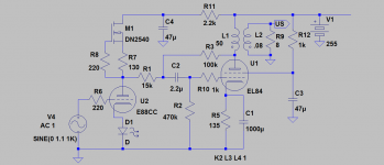
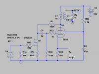
Interestingly enough a DN2540 can be used instead and perfoming a lot, lot better. MJK has a simple solution. See see a AC-version below.
If you still want to go Schade/triode you shouldn´t do it wrongly as in the RH. Did this design for a Belgian member here that reported it sounding great compared to RH. It could without problems be adopted to 807.
Didn´t we discuss this interesting subjecta few years ago?
You get worse dist. figures than me. Probably due to the different and not so good 6AU6 models around.
Anyway 6AU6, as I said is not good, enough for Schade. "Out of steam", like Eric put it, might be a way to describe it.
Interestingly enough a DN2540 can be used instead and perfoming a lot, lot better. MJK has a simple solution. See see a AC-version below.
If you still want to go Schade/triode you shouldn´t do it wrongly as in the RH. Did this design for a Belgian member here that reported it sounding great compared to RH. It could without problems be adopted to 807.
Attachments
Last edited:
Hey Svein,
Didn´t we discuss this interesting subjecta few years ago?
Anyway 6AU6, as I said is not good, enough for Schade. "Out of steam", like Eric put it, might be a way to describe it.
Interestingly enough a DN2540 can be used instead and perfoming a lot, lot better. MJK has a simple solution. See see a AC-version below.
If you still want to go Schade/triode you shouldn´t do it wrongly as in the RH. Did this design for a Belgian member here that reported it sounding great compared to RH. It could without problems be adopted to 807.
Sorry to bring back the past...thanks for the plans. It looks like I will keep my 6AU6 (I bought 5 of them) for a different application..kinda strange that some people say it's not good for Schade but other member report excellent results with 6AU6 and Schade amp...
In your schematics, is the DN2540 used as a constant current source ?
I recently dray a plan for a 6N6P/12AV5GA (poor's man 2A3) using a CCS, this is purely theoretical, just made some holes in my enclosure. I first want to finish improving my RH807 before moving to other stuff.
As always, thanks for the help, I will now read the 6L6 SE link
Eric
Attachments
In your schematics, is the DN2540 used as a constant current source ?
In the left, yes.
The driver will see close to 15kohm load. This technique is not for triode output tube.
some people say it's not good for Schade but other member report excellent results with 6AU6 and Schade amp...
Some DIY:erscould maybe to proud of what they built, not wanting to diss their stuff
") .
.But off course it is also a question about getting all stages in the amp working well together.
And using 6AU6 in PP could be another thing...
About your design two things struck me. 5kohm could be somewhat light loading on 807, 3-4k should be better. Off course 5k is no problem at all. Aren´t you running the 807 to "cold"? Can´t find any Ia figures in your schematic. You can easily run it over 20W Pa. So why not try 250-300ohm Rk? Ca 65mA Ia would give you symmetric clipping with 5k.
Last edited:
My experience with the 6AU6 in a schade amp is based on a clone of the Gary Pimms Tabor amp. A LTP 6AU6 driver runs at about 7mA Ia and drives a pair of 807's in a PP pair. It seems more than capable of driving the 807's, and in this version the amp runs rather high levels of feedback. I respect Gary Pimms expertise and basically copied his operating points with modification to the output bias and the power supply.
I am starting to suspect that what is been described is a bit of bass boost and a bit of distortion. If people like that then all well and good. I built a parafeed version of the RH807 using the ECC81 but never really liked the sound of it and I went onto experiments in PP from which I have never really looked back.
Shoog
About your design two things struck me. 5kohm could be somewhat light loading on 807, 3-4k should be better. Off course 5k is no problem at all. Aren´t you running the 807 to "cold"? Can´t find any Ia figures in your schematic. You can easily run it over 20W Pa. So why not try 250-300ohm Rk? Ca 65mA Ia would give you symmetric clipping with 5k.
I used 5K even though the RH807 specify a 6K load, as we speak the reflected impedance is about 2500 ohm since I'm using 4 ohm spkrs on my 8 ohm OPT.
My 807 could be running too cold, once again having not much experience I used the integral RH807 design which specify a Rk of 400 ohm.
I have 18-19V on the 807 cathode so bias is at about 45mA for a 15W Pa.
I will try to reduce Rk and increase Ia up to 65mA and see if my power supply does not collapse...
Thanks again for all the help
Eric
Hey Eric,
Why on earth following RH. Not the most competent of designs....
2,5k might be on the low side but then you must go for maximum Ia to make it work. 65ma will be good starting point though stil on the low side with this primary Z. Note Ik can be higher as you add screen current to Pa there.
Why on earth following RH. Not the most competent of designs....
2,5k might be on the low side but then you must go for maximum Ia to make it work. 65ma will be good starting point though stil on the low side with this primary Z. Note Ik can be higher as you add screen current to Pa there.
Hi Lars,
I really liked the RH84 so I wanted to try his big brother..
I have now changed Rk to 270ohm instead of 400ohm and this leads to a cathode current of 62mA - a bit from the screen so I am probably around 57mA for the anode.
I have put back the 12AT7 and with this new 'hotter' bias I really enjoy the sound !!
Looks like my issue was the 807 was bias too cold...thanks a lot for all your help.
One last thing I may try one day is to install a switch and use the UL connection on the Edcor.
Based on my calculation Pa is at about 19.5W (80% of max power)
Thanks to all of you for the help.
Eric
Last edited:
Nice Eric!
33k/10k is still a little to hard load on the poor 81. Experiment with a CCS on top of it together with a somewhat bigger seriesresistor. After that try a smaller NFB resistor. And then a more linear tube like E88CC. The 12AT7 has it most linear region at lower current when used in normal triodecircuit.
But use present for quite while, before the next step.
33k/10k is still a little to hard load on the poor 81. Experiment with a CCS on top of it together with a somewhat bigger seriesresistor. After that try a smaller NFB resistor. And then a more linear tube like E88CC. The 12AT7 has it most linear region at lower current when used in normal triodecircuit.
But use present for quite while, before the next step
.Hi,
Regarding your E88CC, it appear that it is identical to a 6922, see here;
JJ E88CC / 6922
But at the same store it looks like the 6N1P is also the same as a E88CC, see here ;
Russian 6N1P
I have a few 6N1P-EV so after checking the pin out maybe I will use it instead of the 12AT7...any comments ?
Thanks again, it sounds awesome. I will probably do these mods later...I will first enjoy my new amp
Rgds,
Eric
Nice Eric!
33k/10k is still a little to hard load on the poor 81. Experiment with a CCS on top of it together with a somewhat bigger seriesresistor. After that try a smaller NFB resistor. And then a more linear tube like E88CC. The 12AT7 has it most linear region at lower current when used in normal triodecircuit.
But use present for quite while, before the next step
Hi Lars,
One more question, how do you size R1 on your left schematic, is there a prefered ratio...it's now 15K but I noticed that another member (Kegger) did a 6AV5 SE schematic and used 8K2 instead of 15K. Is there a rube of thumb, mine is now at 13K ohm.
Thanks,
Eric
Hi Eric,
You have to find the correct driver loadline with the help of the Ua/Ia curves in the data sheet. In short, the load is Ra//seriesR(15k in my case). For an E88CC a CCS//15k will do but even higher R load would be preferable, but not doable.
Too high series resistance make you loose dynamics and top-end response. A CCS has infinite resistance. Lower Ra and series R will worsen distortion figures for the driver.
Recommendations for E88CC NFB: 15k-100k. CCS at 5-10mA. Cathoderesistor must be bypassed or substituted for LED.
Last edited:
Hi,
Thanks for the explanation and bias value.
Well, I hooked up the much improved RH807 in UL mode and I really did not like the sound..kind of wondering if its because there are now 3 feedback working all together ;
1. Un-bypassed Rk on the driver.
2. Schade plate to plate feedback
3. UL connection on screen of 807 instead of Zener regulated 275Vdc.
I reconnected everything and once again I'm a real happy man
I just had to try it, sure glad I did. For me, the UL connection killed all the 'liveness' that I used to have earlier, I felt I was listening to a dead boring SS amp...
p.s. Just got a good pair of RCA 807 since I'm pushing these a bit harder at 20W I needed a back-up set, I also bought a pair of 6W6GT I'm going to try as SET. (I heard the mids are simply unbelievable)
Thanks to all, I'm slowly learning.
Eric
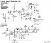
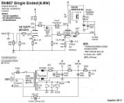
RH807 with cathode feedback
Hi,
Well, what a cool hobby. I was reading lots of great stuff on the 6AV5 for my next project from George at Tubelab (amazing site) and decided to give cathode feedback a try with the RH807 and my Edcor OPT.
Well, it works great !! I did not measure anything but it seems that the output power is slightly more, the mid are better defined. I have one channel normal and the other with CFB. After a few days of listening I will mostly change the amp to cathode feedback. BTW, how do you calculate the value for the feedback cap...I only had 2200uF.
I have attach the schematics but please note that the voltages are from my previous version (not with cathode feedback so disregard the voltages)
Best regards,
Eric
Attachments
Thank you MikeR,
I believe by keeping the 13K (or 15K) and replacing the 33K by a CCS would lead to a higher resistive load for the 12AT7 which is good. The 12AT7 load is Ra//13K or CCS//13K as seen on post no.133
Even when installing a CCS, finding out the series resistor (ex 13K) looks like trial and error to me even with the load line.
I might install later on a CCS as a last improvement but I will make sure to properly measure Ia with an amp meter before switching to a CCS. So far I'm thrilled with the sound. I did some measurement last night and before any sign of clipping with a 1KHz sine wave input gave me 5.8W rms @ 8 ohm with 340Vdc on the plate of the 807.
Regards,
Eric
Nice Eric!
33k/10k is still a little to hard load on the poor 81. Experiment with a CCS on top of it together with a somewhat bigger seriesresistor. After that try a smaller NFB resistor. And then a more linear tube like E88CC. The 12AT7 has it most linear region at lower current when used in normal triode circuit.
But use present for quite while, before the next step
Hi Lars,
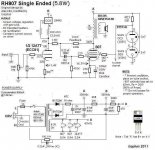
Well I have enjoyed this amp a lot so it was time for some more mods
I have added a CCS on top of the driver and changed the series resistor to 13K, as a last mods I also lowered the local feedback resistor from 150K to 100K. My last mod (waiting for the material) will be to regulate the screen voltage with gas tubes I already ordered from e-bay (russian stuff) but I do not expect much improvement since the screen voltage only vary by about 15-20V on loud passage. I will post again if there is improvement with the gas tubes. (see attached latest schematic)
I may put a pot and vary the driver's current via the CCS and see what's happen but for now I'm enjoying the amp.
p.s. PLEASE feel free to recommend more mods...
I almost forgot...I have a small hum which can be annoying sometime, I measure 8mV AC on a 8 ohm load. Adding an extra 120uF, 450Vdc on the B+ only lower it to 7mV. Before the B+ reaches 350V the hum is at 3.5mV and slowly increases to 8mV as the B+ is becoming stable...kind of odd...
Thanks to all for the help.
Rgds,
Eric
Attachments
Last edited:
Hey Eric,
Why on earth do you still use the, in my eyes unsuitable, 12AT7? The tube can have good linearity at very low currents as shown by SY. But at these currents it will be quite unlinear. Off course distortion cancellation helps but better to use another tube.
Go for the 6N1P(at 5-10mA) you have instead. And go for 15k series resistor.
Hey Eric,
Why on earth do you still use the, in my eyes unsuitable, 12AT7? The tube can have good linearity at very low currents as shown by SY. But at these currents it will be quite unlinear. Off course distortion cancellation helps but better to use another tube.
Go for the 6N1P(at 5-10mA) you have instead. And go for 15k series resistor.
Hi Lars,
I'm still stuck because I do not know what to look for in other suitable driver, I have a few 6N1P, 6N2P and 6N6P double triodes. What would be best is the BIG question
If I have time tomorrow (still on vacation) I will at least try the 6N1P and will keep you posted. Thanks for the help.
Rgds,
Eric
- Status
- This old topic is closed. If you want to reopen this topic, contact a moderator using the "Report Post" button.
- Home
- Amplifiers
- Tubes / Valves
- RH84 SE, pentode driver... advice please