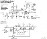
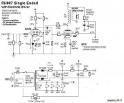
Thank you both for answering, I must admit that this is way over my head...I have modified the schematic and came up with this for the driver;
Tube audio is new to me and I'm hooked big time")
B+ 300V
Rp = 18K
Ia = 7mA
Va = 170V
Rg2 = 150V
Ig2 = 2mA
Rk = 250 ohm
Vk = 2.25V
Ik = 9mA (Ia + Ig2)
I have lower Rp to 18K and therefore left my Rfb similar to before.
Thanks a lot for your help
Eric
Tube audio is new to me and I'm hooked big time
B+ 300V
Rp = 18K
Ia = 7mA
Va = 170V
Rg2 = 150V
Ig2 = 2mA
Rk = 250 ohm
Vk = 2.25V
Ik = 9mA (Ia + Ig2)
I have lower Rp to 18K and therefore left my Rfb similar to before.
Thanks a lot for your help
Eric
Attachments
Hi,
Well I did some test tonight and at least I have some sound with the 6AU6 installed.
My left channel is with the 6AU6 and the other one is with the 12AT7, I can easily compare ;-)
As is like on the last schematics, the gain is much lower with the 6AU6. I then bypassed Rk with a 220uF and now the gain seems way too high, when I turn the volume it does not take much to start distorting. My Rfb is 150K and Rk is 300ohm.
Is there a way to approximate the resistors (Rp, Rk) values to have a similar gain as the original RH807 ?
Thanks for your help.
Eric
Hi,
Well I did some test tonight and at least I have some sound with the 6AU6 installed.
My left channel is with the 6AU6 and the other one is with the 12AT7, I can easily compare ;-)
As is like on the last schematics, the gain is much lower with the 6AU6. I then bypassed Rk with a 220uF and now the gain seems way too high, when I turn the volume it does not take much to start distorting. My Rfb is 150K and Rk is 300ohm.
Is there a way to approximate the resistors (Rp, Rk) values to have a similar gain as the original RH807 ?
Thanks for your help.
Eric
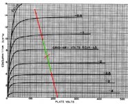
Here's an example based on your circuit values.
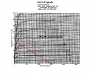
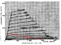
First look at the 807 loadline to get an estimate of the in-circuit gain. Here we have about 4mA/V into 5K load for a voltage gain of approximately 20. Assuming 150K Rfb, the effective load due to Rfb will be 150K/(20+1) about 7143 ohms.
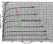
This is in parallel with the 18K plate resistor for an effective plate load of about 5114 ohms. Plotting this slope through your op point of 170V/7mA gives the 6AU6 loadline. I've highlighted the full signal plate swing in green.
The feedback ratio here is the ratio of 6AU6 signal current through Rfb to the total signal current, or about (1/7143)/(1/5114) which works out to .72 or 72% local feedback.
The sensitivity will be about 2.75V P-P plus 7mA * 300 ohms = 2.1V or 4.85V P-P input for full output. This is a little less than 2V RMS if I did everything right
Increasing Rfb will increase the sensitivity correspondingly.Attachments
Last edited:
More changes..
Hi Michael,
I'm not sure I understand about the feedback, are my chosen value good or is the feedback ratio at 72% too high ?
I will try tonight the following 2 versions and keep you guys posted, so far I prefer the sound of the original RH807 with the 12AT7 but this could be simply because I did not properly set-up the 6AU6, any help is welcome.
I will change Rk for 180 ohm (Vk 1.7V) and change Rfb for 270Kohm
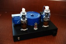
For fun, I have attached a picture of my RH807.
TIA,
Eric
Hi Michael,
I'm not sure I understand about the feedback, are my chosen value good or is the feedback ratio at 72% too high ?
I will try tonight the following 2 versions and keep you guys posted, so far I prefer the sound of the original RH807 with the 12AT7 but this could be simply because I did not properly set-up the 6AU6, any help is welcome.
I will change Rk for 180 ohm (Vk 1.7V) and change Rfb for 270Kohm
For fun, I have attached a picture of my RH807.
TIA,
Eric
Attachments

Hi Michael,
I'm not sure I understand about the feedback, are my chosen value good or is the feedback ratio at 72% too high ?
I will try tonight the following 2 versions and keep you guys posted, so far I prefer the sound of the original RH807 with the 12AT7 but this could be simply because I did not properly set-up the 6AU6, any help is welcome.
I will change Rk for 180 ohm (Vk 1.7V) and change Rfb for 270Kohm
For fun, I have attached a picture of my RH807.
TIA,
Eric
It just means that 72% of the plate signal gets back to the grid as feedback. It puts the effective plate resistance at about 350 ohms. You should have good speaker damping. Changing Rfb to 270K changes the feedback to 58%, resulting in about 430 ohms effective plate resistance. The load line of the driver goes to about 7500 ohms.
Changing Rk and Rfb should increase the sensitivity quite a bit. The Rk change should get you a little more plate current on the 6AU6, maybe getting into a more linear regime. The input sensitivity should be about 1V P-P grid swing plus about (5.5mA * 180) 1V degeneration for 2V total P-P input sensitivity at full output.
Maybe measure Vk, Vg2, Va on both tubes, just to verify all your op points.
Attachments
Last edited:
Schem with measured voltage
Hi,
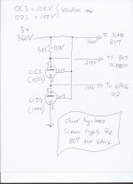
Here is my schematic (exactly as built...for now...) with some measured voltage, hope this helps to figure out why as soon as I turn up the volume the amp start to distort quite rapidly.
Please help
I have a list of planned action but if possible I'd like tube wizard's opinion first.
Regards,
Eric
Hi,
Here is my schematic (exactly as built...for now...) with some measured voltage, hope this helps to figure out why as soon as I turn up the volume the amp start to distort quite rapidly.
Please help
I have a list of planned action but if possible I'd like tube wizard's opinion first.
Regards,
Eric
Attachments
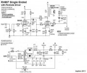
There is nothing terribly wrong with the voltages.
I do however get somewhat different values with LtSpice simulation. That could be due to the tube simulation model, but it could also be some wiring error or other difference between schematic and the real thing.
Could you please double check that the Rfb is connected as shown, and not to the other side of coupling cap.
Edit: Your voltages and currents do seem to add up. The difference in readings must therefore be my Spice model, or your tube being a bit outside the typical rating.
SB
Last edited:
Hi Svein,
For simulation purpuse I have RCA 6AU6WA and the 807 is also RCA.
The only difference I could think is the 166V on 6AU6 Vg2 comes from the 3rd zener of a 5 zener string to get to 275V on the 807 screen, I taped myslf at the third one which gives me 166Vdc. The rest of the schematic is identical.
Thanks all for your help, this is much appreciated.
Regards,
Eric
With the 6au6 screen supplied from a 166V source, the other voltages match close to my simulation.
The simulation gives about 9W power before the distortion approaches 5%.
Performance will be slightly better with Rk=180 and B+ about 300V, but this is a minor tweak, once you are satisfied with the basic design.
The bypassed Rk gives a bit more distortion from the driver stage than unbypassed, but lower overall distortion due to some distortion cancellation.
SB
The only difference I could think is the 166V on 6AU6 Vg2 comes from the 3rd zener of a 5 zener string to get to 275V on the 807 screen, I taped myslf at the third one which gives me 166Vdc.
I wonder if the total current on the zener string is more than ~8 mA on peaks, and the g2 voltages are dropping out. Do you have bypass caps on the g2 connections?
Last edited:
Hi,
This is very encouraging.
I will try : Rk=180 and B+ about 300V
I am not certain about the zener current but the screen of 807 takes about 8mA at max power. I will add a bypass cap on the 6AU6 g2 connections. There is no voltage drop on the 807 screen since I have a 47uF bypass cap.
Once this amp sings with the 6AU6, I will replace Rk and Ck on the driver for a 1.6-1.8V LED and see how it sounds.
Thanks for the helps.
Eric
I did some more test, it getting better but not as good as the original RH807 with the 12AT7.
Now I have the following for the driver ;
B+ is at 288V
Vplate is a bit lower at 166V.
Vk is 1.86V with Rk as 180ohm.
Vg2 is 158V with the addition of a 22uF bypass cap.
I have removed the driver bypass cathode cap, with it the distortion would rise so quickly, if the volume was at 2pm it was awful...
Both channel now play just as loud but the one with the 12AT7 has more bass and the bass is better controlled...the 6AU6 side sounds very thin but the mid sounds more detailled.
Oh well, so far I'm not convinced that using a pentode as a driver instead of a triode on the RH807 is better and will do the trick for me. My speakers are MUCH better controlled (no sloppiness) with the original RH807 and before distorsion is heard the original RH807 played louder.
Eric
Hi,
I believe my screen are running out of steam so as a last resort I could buy some voltage reg tube and built some glow tub reg, see schematic I actually took from this forum.
With the 6AU6 in place it looks like one side of the amp is rated 2W and the one with the 12AT7 is about 5W, this would explain the annoying early distortion from the pentode driver...
Thanks,
Eric
Attachments
I did some more test, it getting better but not as good as the original RH807 with the 12AT7.
Now I have the following for the driver ;
B+ is at 288V
Vplate is a bit lower at 166V.
Vk is 1.86V with Rk as 180ohm.
Vg2 is 158V with the addition of a 22uF bypass cap.
I have removed the driver bypass cathode cap, with it the distortion would rise so quickly, if the volume was at 2pm it was awful...
Both channel now play just as loud but the one with the 12AT7 has more bass and the bass is better controlled...the 6AU6 side sounds very thin but the mid sounds more detailled.
Oh well, so far I'm not convinced that using a pentode as a driver instead of a triode on the RH807 is better and will do the trick for me. My speakers are MUCH better controlled (no sloppiness) with the original RH807 and before distorsion is heard the original RH807 played louder.
Eric
You will be getting lower output impedance with the pentode driver - which means better damping and hence better bass control. Often this is perceived as worse/less bass when infact it is an amp-speaker artefact.
Very interesting.
For your screen drive you could try a simple transistor current boost off of the zener string. take the zener node to the base and use a 1K resistor to the collector and the emittor to the g2. Simple.
Shoog
Last edited:
You will be getting lower output impedance with the pentode driver - which means better damping and hence better bass control. Often this is perceived as worse/less bass when infact it is an amp-speaker artefact.
Shoog
With the value I have on my schematics it's not a perception...even my son who was near by told me to quickly lower the volume. Have you done a side by side comparison ?
So far the sound on both side (left side pentode driven and right side triode driven) is similar except that the triode side has a much richer sound while the pentode side is thin sounding, my biggest concern is that now the 6AU6 side as a much lower output power while the 12AT7 side is still nice and strong...why...which value should I change to correct this ?
Thank you all for your help.
Rgds,
Eric
One must leave the driver cathode unbypassed.So far so good.
What you define as richer sound from the 12AT7 could as well be the higher distortion from this one.
As Shoog says "thin sound" could be the better control of the speaker due to lower Zout.
Also the remember 6AU6 is far from the ideal driver. E280F or D3a are great.
The interaction between OPT inductance, output tube cathode cap, the driver screencap and coupling cap can lead to lowfrequency boost. Have you measured both versions?
Last edited:
I tried to compare the latest pentode driver circuit with the original RH807 circuit in LtSpice. Pentode circuit with unbypassed RK=180.
I believe the output impedance is an indicator of the effectiveness of the feedback.
In order to get the same output impedance, I found that the Rfb should be 100K also for the 6AU6 version.
Output impedance = 2.3 ohm (Using a fictional 5K OPT with primary inductance 15H, primary R=100 ohm, secondary R=0.1 ohm.)
Distortion is about the same for both circuits;
about 0.6% at 1W (2'nd dominant), and 2-3% at 7W (3'rd a little higher than 2'nd)
Edit: For reference, the output impedance for triode strapped output tube is 2.7 ohm with the same fictional OPT as above. Max power less than 3W, and distortion way higher.
SB
Last edited:
One must leave the driver cathode unbypassed.So far so good.
Also the remember 6AU6 is far from the ideal driver. E280F or D3a are great.
I simply bought a few 6AU6 because Shoog mentioned he had great success with this tube in Schade amp, maybe I should use a different one (maybe the EL84, I love this tube and have quite a few). Looks like the 6AU6 is running out of steam to drive the 807...but the 12AT7 is doing a fine job despite the bass boost. A agree that there is probably a boost with the 12AT7 this is why the 6AU6 sound thin sounding..my problem remains..time to get my generator and scope to see the reason for such a reduced output power using the pentode driver vs the triode driver. I must have the wrong value around the driver, feel free to suggest adequate values
Thanks all for your help, I will work on the amp next week.
Eric
FWIW I have built several RH84 with 12AT7 and two with 6AU6. I played endlessly with the op points for the 6AU6 and with regulation ect. In the end I always liked the 12AT7 better. Maybe it was the distortion that sounded better to me but at the end of the day distortion or not what pleases you is what's better no? I would really love to see some plate curves of the 12AT7 with an un-bypassed Rk at this op point, just wondering how pentode-like they might look as hinted to by a previous poster in this thread. As always YMMV, IMHO and so on...
- Status
- This old topic is closed. If you want to reopen this topic, contact a moderator using the "Report Post" button.
- Home
- Amplifiers
- Tubes / Valves
- RH84 SE, pentode driver... advice please