Hi,
I built 2 years ago a RH84 according to Alex's plan using the 12AT7 and to this day it is my favorite amp. (I have also recently built a Chinook amp 13FD7 SET and RH807)
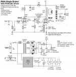
I have modified Alex's plan and ordered last night some 6AU6 JAN type. I have attached my schematics, please comment and recommend something better before I start making holes in my 10 x 6 chassis. Most comments for the pentode driver comes from a post by Shoog..this is why his name is on the plan (I do not like to take credit for someone else work.)
Thanks in advance,
Eric
I built 2 years ago a RH84 according to Alex's plan using the 12AT7 and to this day it is my favorite amp. (I have also recently built a Chinook amp 13FD7 SET and RH807)
I have modified Alex's plan and ordered last night some 6AU6 JAN type. I have attached my schematics, please comment and recommend something better before I start making holes in my 10 x 6 chassis. Most comments for the pentode driver comes from a post by Shoog..this is why his name is on the plan (I do not like to take credit for someone else work.)
Thanks in advance,
Eric
Attachments
Last edited:
Looks good to me.
The only two comments I would make is;
-its a very good idea to regulate the driver stage as you have done, though I would be inclined to use 10V zeners in the critical range so that you can home in on the 6AU6 sweet spot for this circuit. The way I have done driver screen regulation before is to use a resistor string and a multi-turn pot feeding the base of a transistor. Pass 1mA through the string and use a high hfe transistor (MJE350 should do) and you have a totally adjustable screen supply which shouldn't vary much with screen current and will not introduce zener noise at a critical junction.
-regulating the output stage produces very little benefit in this circuit in my experience - though it is unlikely to hurt.
Shoog
Looks good to me.
The only two comments I would make is;
-its a very good idea to regulate the driver stage as you have done, though I would be inclined to use 10V zeners in the critical range so that you can home in on the 6AU6 sweet spot for this circuit. The way I have done driver screen regulation before is to use a resistor string and a multi-turn pot feeding the base of a transistor. Pass 1mA through the string and use a high hfe transistor (MJE350 should do) and you have a totally adjustable screen supply which shouldn't vary much with screen current and will not introduce zener noise at a critical junction.
-regulating the output stage produces very little benefit in this circuit in my experience - though it is unlikely to hurt.
Shoog
In his circuit, he's regulating the screen and not the driver or output stage.
The fuse on the secondary has no purpose. See Morgan Jones.
Also. I would be nervous of RF interference with the SMPS feeding the heaters. And maybe you need a 1M resistor in the input tube grid, in case the pot scraper lifts?
A choke in the power supply would be much nicer too.
Also. I would be nervous of RF interference with the SMPS feeding the heaters. And maybe you need a 1M resistor in the input tube grid, in case the pot scraper lifts?
A choke in the power supply would be much nicer too.
Hi All,
Thanks for the feedback.
Fuse on secondary are quite useful IMO, in case one of these 450Vdc cap becomes short-circuit or partial short-circuit the secondary fuse blows instead of having a dead power transformer. How can a fuse have no purpose ?
For the SMPS feeding the heaters my original RH84 is dead quite and I have not noticed EMI interference but I'll keep this in mind. Good idea about the grid resistor to gnd, it's there already but not on schematic.
My original RH84 is tube rectified with 5U4 + choke (8H, 125mA, Rdc = 150ohm from Radiodaze)
For the choke in the PS, besides having a smaller ripple is there any sonic advantage ?
Efharisto poly, my in-laws are from Greece ;-) Thanks,
Eric
i run smps for heater powering too. never had even a bit of noise/etc. runs great. I run a similar tube amp to this one just no 'local feedback' connection and fixed bias
substitute 7868 with an 807
running a 5 channel monster myself,")
pentode driver stage is an interesting idea. ill have to try it out some time
An externally hosted image should be here but it was not working when we last tested it.
substitute 7868 with an 807
running a 5 channel monster myself,
pentode driver stage is an interesting idea. ill have to try it out some time
Last edited:
your primaries are more likely to be damaged then your secondary windings from my understanding. Also it wouldnt protect against a internally shorted transformer, you'd be setting something on fireFuse on secondary are quite useful IMO, in case one of these 450Vdc cap becomes short-circuit or partial short-circuit the secondary fuse blows instead of having a dead power transformer. How can a fuse have no purpose ?
Last edited:
Have a quick question. The amp, which has been running beautifully for a few months, has suddenly developed a buzzing sound coming from *inside* the chassis (not through the speakers). I've narrowed it down to the power transformer (Lundahl 1683). It comes on after about an hour of use and stays; it's a pretty loud mechanical buzz, rather than a hum. Any ideas?
Hi Shoog,
If it looks good to you then I'm going to built it as is. Can't wait to hear the difference between a RH pentode driven vs triode driven. Will take a few weeks to build since I just ordered my 7 pin tube socket from e-bay (China)
I hope my schematic can be useful for someone else, while looking at this site I hadn't found any actual schematic of RH84 pentode driven.
Once done I will try to modify my RH807, to this day, I never really went crazy about the sound although I'm really impressed with the RH84 with 12AT7. With the RH807, it's like the mid are covered with a blanket. With the same speaker my RH84 sounds much better.
Does someone have a schematic of the RH807 with a pentode driver ?
Thanks,
Eric
Hi Shoog,
If it looks good to you then I'm going to built it as is. Can't wait to hear the difference between a RH pentode driven vs triode driven. Will take a few weeks to build since I just ordered my 7 pin tube socket from e-bay (China)
I hope my schematic can be useful for someone else, while looking at this site I hadn't found any actual schematic of RH84 pentode driven.
Once done I will try to modify my RH807, to this day, I never really went crazy about the sound although I'm really impressed with the RH84 with 12AT7. With the RH807, it's like the mid are covered with a blanket. With the same speaker my RH84 sounds much better.
Does someone have a schematic of the RH807 with a pentode driver ?
Thanks,
Eric
The substitution of a pentode as the driver is based on the theoretical improvement it will bring. Having someone who can do a side by side comparison will help to clarify if the theory is supported by the facts and therefore you are doing the whole community a great service in trying the experiment.
I built a RH807 with a parafeed output stage as my first amp. I didn't like the result that much and moved onto PP amps. One of my current amps is a copy of Gary Pi,mms direct coupled Tabor amp using 807's. It sounds sweet and proves that the 807 can be made to sing in a Schade arrangement.
I very much look forward to hearing your impressions once the build is complete - Good Luck.
Shoog
I built this amp as one of my first projects. Its not great as it stands, and Kitic was less than helpful with information - another comudgeon.
Running the front end as a pentode is "essential" for getting this to work properly, and indeed the 6AU6 is the boy to do it.
That should get you going - and can be fine adjusted if necessary. This will sound infinitely better than the original.
Things work out better if you have a B+ of 350V.
Shoog
Hi Shoog,
I guess I misunderstood, it actually looked like you had tried and heard the modified RH84 with a pentode as a driver.
At least now thanks to you I have some great guideline and value to start with the 6AU6, I will keep you posted.
Rgds,
Eric
Hi Shoog,
I guess I misunderstood, it actually looked like you had tried and heard the modified RH84 with a pentode as a driver.
At least now thanks to you I have some great guideline and value to start with the 6AU6, I will keep you posted.
Rgds,
Eric
I have built a number of schade amps with pentode drivers so I do speak with experience. I have used the 6AU6 with excellenet results.
Shoog
RH807 pentode driven.
Hi,
There was a postal strike here in Canada so I have just received my 6AU6WA (man, these tubes are so small...), I'm ready to give this amp a try but it would be much easier for me to modify the hardware of my RH807. I have modify the original RH807 schematic and inserted a 6AU6 instead of the 12AT7, could someone comment and verify my new value (Ra, Va, Rk, Vk, etc.) I just want to make sure I'm aiming at the good direction. The load line for the 6AU6 are very flat at around 2-2.5V (Vg) but how about the required current through the anode..so the 6AU6 can sing...
Thanks a lot for your help, I can't wait to see what this is all about.
p.s. Sorry about talking about the RH807 but I believe the RH84 or 807 will give similar sound signature.
TIA,
Eric
Attachments
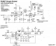
Since the driver will be relatively high impedance (~30K) you should probably increase the value of the feedback resistor to 250-300K to get a feedback voltage ratio of about 1/10 (as recommended by Shade).
Alternatively you may consider using a lower value anode resistor for the 6AU6, and corresponding adjustment to Rk and Rg2.
The AC load line for the 6AU6 will be much steeper than the DC load since the Rfb will represent a dynamic load corresponding to about 1/15 of its value.
From the 6AU6 curves it looks like it will be most linear with an anode current of 7-8 mA.
--
SB.
Attachments
RH feedback ratio revisited
The portion of the driver's signal current swing that goes through Rfb is feedback. The portion that goes through the anode resistor is not.
Thus, the feedback ratio of the RH style feedback circuit must be calculated based on the ratio of the dynamic Rfb load vs the static anode resistor. A Svein points out, this is a small fraction of the Rfb component value ("about 1/15").
The dynamic Rfb is actually Rfb/(1+output_tube_gain) which is, not coincidentally, the same equation used to estimate the Miller effect.
So, if the Rfb is 330K and output tube gain is (guessing) 14x grid to plate, the dynamic Rfb is 330K/15 or about 22K. If the anode resistor is 33K, then the feedback ratio is going to be the ratio of driver current swing over Rfb vs. total driver current swing (1/22K)/((1/22K)+(1/33K)) = 0.6, or 6/10.
It follows that using a gyrator with high dynamic impedance in place of the anode resistor causes the feedback ratio to approach 1.0 or 100%. At 100% feedback, the output impedance approaches 1/gm, the same as a cathode follower.
6-8 mA is IME the sweet spot for the 6AU6 in this application.
Cheers,
Michael
Since the driver will be relatively high impedance (~30K) you should probably increase the value of the feedback resistor to 250-300K to get a feedback voltage ratio of about 1/10 (as recommended by Shade).
Alternatively you may consider using a lower value anode resistor for the 6AU6, and corresponding adjustment to Rk and Rg2.
The AC load line for the 6AU6 will be much steeper than the DC load since the Rfb will represent a dynamic load corresponding to about 1/15 of its value.
From the 6AU6 curves it looks like it will be most linear with an anode current of 7-8 mA.
--
SB.
The portion of the driver's signal current swing that goes through Rfb is feedback. The portion that goes through the anode resistor is not.
Thus, the feedback ratio of the RH style feedback circuit must be calculated based on the ratio of the dynamic Rfb load vs the static anode resistor. A Svein points out, this is a small fraction of the Rfb component value ("about 1/15").
The dynamic Rfb is actually Rfb/(1+output_tube_gain) which is, not coincidentally, the same equation used to estimate the Miller effect.
So, if the Rfb is 330K and output tube gain is (guessing) 14x grid to plate, the dynamic Rfb is 330K/15 or about 22K. If the anode resistor is 33K, then the feedback ratio is going to be the ratio of driver current swing over Rfb vs. total driver current swing (1/22K)/((1/22K)+(1/33K)) = 0.6, or 6/10.
It follows that using a gyrator with high dynamic impedance in place of the anode resistor causes the feedback ratio to approach 1.0 or 100%. At 100% feedback, the output impedance approaches 1/gm, the same as a cathode follower.
6-8 mA is IME the sweet spot for the 6AU6 in this application.
Cheers,
Michael
- Status
- This old topic is closed. If you want to reopen this topic, contact a moderator using the "Report Post" button.
- Home
- Amplifiers
- Tubes / Valves
- RH84 SE, pentode driver... advice please