wakibaki said:It'll be a big capacitance or inductance that isn't swamped by 75R.
w
100pF isn't swamped by 75R
") Even at slow 44.1 KHz rate.
Even at slow 44.1 KHz rate.With HiFace and 192 KHz it should look much worse
Attachments
Last edited:
Dear Sy,
I have already posted that in this thread, here:
http://www.diyaudio.com/forums/digi...ttenuators-jitter-reducers-8.html#post2226135
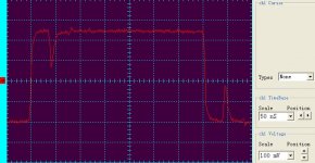
The first shot is a hiface > 75ohm line > 75ohm (or so..) termination, without attenuator.
OK, so your trace of the unattenuated output of the Hiface and mine look the same. Now, what is the problem in your setup whereby the attenuators are not delivering an exact scaled-down version of that waveform?
Sy, that is not a problem, that was on purpose: to be able to compare, I have "normalized", brought back to the same level the attenuated signal. And told so explicitly, before.
As you see, the only diffeence is the attenuator. The traces are normalized, so as to see the same percentage of the reflections.
Last edited:
Yeah, fine, where's 100pF gonna come from? You'll never get 100pF as strays, 2 or 3 maybe, at most 10 and that's unlikely. 10nH of inductance. Like I told TNT; be realistic. You're just stretching things beyond the feasible because the idea that somebody might see off the top of their head that using a DMM is perfectly adequate freaks you out. I didn't come down with the last shower of rain you know. I been doin' this **** for years.
w
w
Yes, but the attenuation is now frequency dependent.
I don't understand this, could You explain, please?
DO You really think that adjusting the variable gain (by 3 times) of the very same oscilloscope channel (> 500MHz in that shot)
will change the response with any important amount? (I did not see any change while doing that, as one should not, on a TEK scope)
Last edited:
Sy, I can not follow You here.
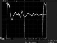
I had attenuated the signal with pretty good attenuators.
Then re-amplified with a pretty high bandwith amplifier.
The results visible in the shots fit ~perfectly, what regards the edges.
Where is it that I am lost?
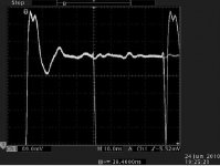
I had attenuated the signal with pretty good attenuators.
Then re-amplified with a pretty high bandwith amplifier.
The results visible in the shots fit ~perfectly, what regards the edges.
Where is it that I am lost?
Attachments
Last edited:
I'll ask again does it sound exactly the same as my Hiface?
Since it's been in my lab all weekend, I'll not try to guess. ESP isn't my strong point.
Where is it that I am lost?
It's not where you get lost, it's where you stopped.
If an ideal attenuator has a scalar transfer function (e.g., 0.5 for a 6 dB attenuator), the output waveform will look identical to the input waveform. Now you could deliberately manipulate the length of cable used in the measurement and its termination to cause an antiphase reflection and partially null some of the lower level higher frequency mixture riding on the top, but not only is that a poor solution, it's a solution to a problem that doesn't appear to be a problem.No, Sy, I don't see any problems with that method of mine, sorry. After scaling down and going back with much higher bandwith than the signal has, one should simply get back the original waveshape.
Edit: now I see your edited text.
Please, do not accuse me with anything of falsification, in that test I did not do anything else that had been documented, (inserting an attenuator) and I had even described earlier why it is happening.
Your objections are not valid, sorry.
Edit: now I see your edited text.
Please, do not accuse me with anything of falsification, in that test I did not do anything else that had been documented, (inserting an attenuator) and I had even described earlier why it is happening.
Your objections are not valid, sorry.
Last edited:
No, Sy, I don't see any problems with that method of mine, sorry. After scaling down and going back with much higher bandwith than the signal has, one should simply get back the original waveshape.
And you don't. Do the waveforms overlay? Nope.
Then why are these "reflections" not present with a cheap Chinese unit measured exactly the same way (except for plugs/jacks)? Is it a black hole? And why are the relative size of these "reflections" identical in my measurement with and without the attenuator on the Hiface, as would be expected from proper cable and termination?
Of course, from the important standpoint of what analog signal emerges from all of this, none of these issues seem to matter.
Of course, from the important standpoint of what analog signal emerges from all of this, none of these issues seem to matter.

Sy,
I had just responded to this question ~20 posts ago..
I had just responded to this question ~20 posts ago..
Sy,
Very good that You brought it up:
The difference is that Your cheap Chinese transmitter is having a rise time at about 6nsec. That is ~58MHz equivalent bandwith.
The hiface driver is having 1.5 nsec rise time in reality. (measured by me on 6GHz, 3,5GHz, 2GHz analog bandwith scopes)
Pardon, the most recently tested unit had less than 1nsec rise time. The older one is 1.5nsec.
At this speed (1.5nsec > ~250MHZ, 1nsec >350MHz ) your test setup has to be much more refined so as not to cause reflections. This is the difference what You see.
This is the unit I used for a low-rent comparison:
USB Port Mini Converter SPDIF Coaxial Output DAC - eBay (item 250637376165 end time Nov-18-10 04:21:10 PST)
USB Port Mini Converter SPDIF Coaxial Output DAC - eBay (item 250637376165 end time Nov-18-10 04:21:10 PST)
- Status
- Not open for further replies.
- Home
- Source & Line
- Digital Source
- RF Attenuators = Jitter Reducers