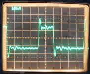
Repeated the above measurement with a 4kHz tone to see if I could get the spurs that Pano saw with his DCX. Yes, some appeared, though far fewer than he saw- the worst one was at -85dB somewhere around 12kHz or so. The passive output mod is looking even more attractive...
In any event, the baseline didn't fuzz up, no difference whatever in the spectra of the analog output between the Hiface and the Chinese unit as USB -> spdif converters.
In any event, the baseline didn't fuzz up, no difference whatever in the spectra of the analog output between the Hiface and the Chinese unit as USB -> spdif converters.
Ok, so jitter is 4kHz. Would expect one at 18.9kHz then too. Maybe the measurement doesn't go that far. And jitter exactly 4000Hz. Where is that coming from?? I've only looked at XO jitter and that's not at just one freq. Must be something caused by the spdif transmitter, right?
Btw, googled a bit on bessel and spur") One of the hits was pll performance and reference spurs caused by a pll (national presentation). Are we not seeing this from the pll from the spdif receiver ?
One of the hits was pll performance and reference spurs caused by a pll (national presentation). Are we not seeing this from the pll from the spdif receiver ?
Btw, googled a bit on bessel and spur
One of the hits was pll performance and reference spurs caused by a pll (national presentation). Are we not seeing this from the pll from the spdif receiver ?Ok, so jitter is 4kHz.
No, that's the analog test signal.
Quite correct! My typo. It should be 11Khz - I fixed it.Discussing the picture in post 513, which shows a 10kHz signal i think(alltough the text says 1kHz).
That is a signal with recorded jitter, so I can't take it out. I just wanted a known jitter to see if I could find it in the analog signal. SY, I think you have that same jitter file.
Thanks for posting that measurement. The only thing that really remains is to test the DACs that are said to have shown improvement with the attenuators or the Hiface.
Surprising that the nasty old DCX isn't worse for jitter. Gives me a warm fuzzy feeling 'cause I've been telling a lot of people not to worry too much about the digital side, fix the analog outputs first.

Well, if they do a worse job of handling spdif inputs than the relatively inexpensive DCX, I might wonder what all the extra money is going for. Not that I'm a cynic, mind you...The only thing that really remains is to test the DACs that are said to have shown improvement with the attenuators or the Hiface.
@jkeny:
"I'm not sure what you mean Pano - just terminate the RG59 cable with a 30ohm to 50ohm resistor (typical RCA impedance, I think) instead of the 72R as SY has used in his test set-up & test again!"
There seems to be a lot of confusion about "characteristic impedance" and termination etc, which isn't helping the argument!
RG59 has a 75R characteritic impedance by design (physical dimensions and dialectric). You check it by looking it up in the Belden book!
Of course this cannot be measured with any static meter as it is open-circuit! Hopefully!
It does mean that if driven by a generator with a source impedance of 75R and loaded with an equivalent impedance of 75R it will be a "good" transmission line and not cause reflections.
How to get a 75R source? Classically use a low (~ zero) impedance amplifier and add a series 75R, OR a high Z generator and parallel 75R. Both of these may be measurable with a DVM, as alluded to earlier.
75R load? Pad or shunt what the real load impedance is to get to 75R. That's it! Of course, problems can start to happen with "logic" I/O where the impedance changes as the level transitions.
An RCA has no defined impedance and can be anything. Trying to add a "terminator" to "match" this unknown is a complete unreproducable waste of time. Fortunately the physical length of the impedance error due to an RCA on a realistic length of RG59 is very small, but it cannot be compensated for by sticking a resistor anywhere!
As suggested, the effect of an RCA in a proper transmission line is best analysed using a TDR 'scope.
Mmm,
Starting to get it, did not read all of this post (too much). So the plot is of a source with jitter in it. And deliberately a lot of it, so these spurs occur. Check. But with source i guess you mean a WAV file?
But would this reduction of jitter of 4000Hz prove anything (if it works)?
It's jitter in the signal transported over spdif, showing up at the analog side.
The jitter we try to reduce (of the recovered clock of the spdif i/f) is at a different level. Would it not affect a single frequency (signal without delibarate jitter) or this signal with multiple frequencies created by the jitter in the signal in the same way??
EDIT: "I just wanted a known jitter to see if I could find it in the analog signal"
Ah, ok. Get it. You are not going to use the signal with jitter for your test.
But are you shure you can also detect spdif clock jitter, as it would be different from this single 4000Hz in frequecie(s) and level?
Maybe 4000Hz is a few Hz..
Last edited:
... Hawksford has a paper relating jitter to bandwidth which I could find if you want..
Please post if possible.
Dear Sy,
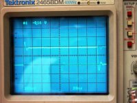
I have just seen Your scope shots. Something is not right here. I think You should go ahead and try until You reach at least the same results what I have done and Jkeny's friend has done. Because the Hiface driver does not have any ringing and other problems, it's superbly clean with respect to a lot of other drivers. I mean, apart from the initial - and only - overshoot. Which is not ringing, it's an overshoot.
(that is, I could go deeper and show "structures" in the signal but not at this level.)
By the way, I think to see in your scope shot a lot of reflections.. or ringing caused by your scope probe.
The order is: Jkeny's friend then mine then Yours.
I'm not attacking You, but now we are talking about simple and hard facts, this is the entry level, if we can not get a common starting point here then we will not get anywhere.
Ciao, George
Attachments
Last edited:
It'll be a big capacitance or inductance that isn't swamped by 75R.
w
At 10ish Mhz?
George, did you see the traces for the Chinese unit? Same probe, same setup except with RCA. If I were to guess, it's the transformers in the Hiface. I think John may have also mentioned the same thing.
Just for review, please repost your scope traces for the Hiface (not the HP) without attenuators with a 75 ohm (or so) line and a 75 ohm (or so) termination. Thanks!
Just for review, please repost your scope traces for the Hiface (not the HP) without attenuators with a 75 ohm (or so) line and a 75 ohm (or so) termination. Thanks!
Dear Sy,
I have already posted that in this thread, here:
http://www.diyaudio.com/forums/digi...ttenuators-jitter-reducers-8.html#post2226135
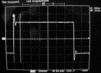
The first shot is a hiface > 75ohm line > 75ohm (or so..) termination, without attenuator.
Or so means that the config in detail is: HIface > 75ohm line > 75ohm bnc bias tee - 75ohm termination, good quality. The scope input is 1Mohm, as should be.
The application of the BNC tee is the factor which upsets (only a bit) the termination, so that it's not perfect low return loss any more.
If it would be, then there would not be anything to measure - if at least one end of the transmission line absorbs the signal perfectly, then there is no chain of repeated reflections created. This is what never happens in a real life SPDIF application.
I have already posted that in this thread, here:
http://www.diyaudio.com/forums/digi...ttenuators-jitter-reducers-8.html#post2226135
The first shot is a hiface > 75ohm line > 75ohm (or so..) termination, without attenuator.
Or so means that the config in detail is: HIface > 75ohm line > 75ohm bnc bias tee - 75ohm termination, good quality. The scope input is 1Mohm, as should be.
The application of the BNC tee is the factor which upsets (only a bit) the termination, so that it's not perfect low return loss any more.
If it would be, then there would not be anything to measure - if at least one end of the transmission line absorbs the signal perfectly, then there is no chain of repeated reflections created. This is what never happens in a real life SPDIF application.
Last edited:
At 10ish Mhz?
Well, unless somebody has put one in there (and what possible reason would there be for doing that), we're talking strays. Be realistic.
w
Sy,
Very good that You brought it up:
The difference is that Your cheap Chinese transmitter is having a rise time at about 6nsec. That is ~58MHz equivalent bandwith.
The hiface driver is having 1.5 nsec rise time in reality. (measured by me on 6GHz, 3,5GHz, 2GHz analog bandwith scopes)
Pardon, the most recently tested unit had less than 1nsec rise time. The older one is 1.5nsec.
At this speed (1.5nsec > ~250MHZ, 1nsec >350MHz ) your test setup has to be much more refined so as not to cause reflections. This is the difference what You see.
Last edited:
no difference whatever in the spectra of the analog output between the Hiface and the Chinese unit as USB -> spdif converters.
Now that's a shock! And I know I'm stupid for even asking this but I have to get you to answer this - you have listened to both of these USB - SPDIF converters, right & they both sound exactly the same, right?
Just for fun, SY, would you try the with/without attenuators using a standard probe?SY said:George, did you see the traces for the Chinese unit? Same probe, same setup except with RCA. If I were to guess, it's the transformers in the Hiface. I think John may have also mentioned the same thing.
The Hiface SPDIF transformer causes the overshoot certainly but don't know about the rest.
- Status
- Not open for further replies.
- Home
- Source & Line
- Digital Source
- RF Attenuators = Jitter Reducers