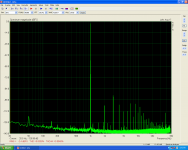
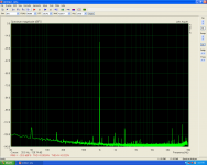
Hi Valery,idle is already 31mA/piece=62mA/pair.Hi Thimios, thank you for the spectrums - looking good.
I think overall distortion level may be even lower if you roughly double the bias - as I remember, my optimum value was 62.5mA of idle current per output pair.
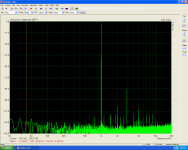
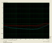
It's interesting that distortion level is rather consistent throughout the bandwidth.
Cheers,
Valery
")
I have something interesting too.
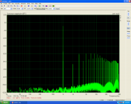
Another test using a real speaker as load.
Last edited:
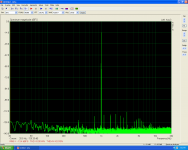
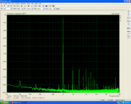
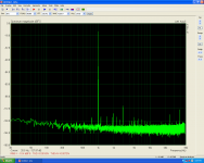
AX-Deluxe FFT Test.
Using a real 3way speaker as load.
Using a real 3way speaker as load.
Attachments
Last edited:
Hi Valery,idle is already 31mA/piece=62mA/pair.
I have something interesting too.
Another test using a real speaker as load.
Emmm... in the complementary pair, transistors (as well as emitter resistors) are connected in series. Meaning that the voltage drop across those resistors sums up, but the current stays the same.
So, you need to have 14mV across each 0.22R resistor, or 28mV across 2 resistors in series
Emmm... in the complementary pair, transistors (as well as emitter resistors) are connected in series. Meaning that the voltage drop across those resistors sums up, but the current stays the same.
So, you need to have 14mV across each 0.22R resistor, or 28mV across 2 resistors in series
What a stupid fault!
Sorry,i will test again.
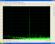
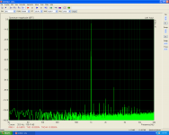
AX-Deluxe New Bias
17mA/0.22R Looks like the optimum.
17mA/0.22R Looks like the optimum.
Attachments
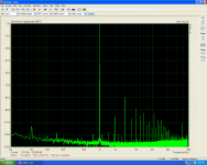
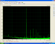
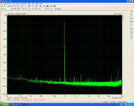
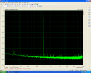
Harmonics 2 and 3 with dominant 3, but rather low absolute values and rather clean high-order areas. I like the way it looks. The amp is also rather tolerant of bias variations - previous measurements with less than 50% bias setting are still good enough
Did you audition the thing?
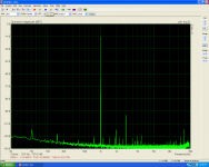
It will be interesting what TubSuMo front-end is going to show under the same conditions.
Did you audition the thing?
It will be interesting what TubSuMo front-end is going to show under the same conditions.


Just for a little but not on main speakers(i haven't protection board yet).Harmonics 2 and 3 with dominant 3, but rather low absolute values and rather clean high-order areas. I like the way it looks. The amp is also rather tolerant of bias variations - previous measurements with less than 50% bias setting are still good enough
Did you audition the thing?
It will be interesting what TubSuMo front-end is going to show under the same conditions.
I think that is a nice sounding IPS.
When i will have the TubSumo on hand we will know the difference.
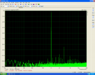
That's why we run the test!Distortion numbers look better with a speaker attached. I though it would be the other way around.
Real world is different than simulations.
Nice built!My build is coming along nicely. That is the NS OPS with Vertical CFA IPS
Here's the regulator PCB
View attachment 647350
View attachment 647351
Here's the Vertical CFA
View attachment 647352
View attachment 647353
I'm pretty happy so far. I'm also working on another project at the same time but it is a headphone amp.
Ciao!
Do
Probably is a new version of the power supply.
or increase the input emitter degeneration,Today tried the MAT02 as input pair but without success.
I see a big distortion level at low volume due to oscillation?
hfe=860,probably the input stage current is realy big and must be lowered?
or do both, i.e. increase degen and reduce Ic.
Hi Thimios,
Are you sure the pinout is correct (I mean, the CBE leads are connected as expected)?
Input stage current is around 1.3mA per collector and it does not depend on hFE of the pair.
By the way, hFE of 2N5089 you used initially is normally around 1000.
So, my guess is the wrong pinout
Cheers,
Valery
Are you sure the pinout is correct (I mean, the CBE leads are connected as expected)?
Input stage current is around 1.3mA per collector and it does not depend on hFE of the pair.
By the way, hFE of 2N5089 you used initially is normally around 1000.
So, my guess is the wrong pinout
Cheers,
Valery
Because i haven't any 2N5089 i used 2N5088 in my board.Hi Thimios,
Are you sure the pinout is correct (I mean, the CBE leads are connected as expected)?
Input stage current is around 1.3mA per collector and it does not depend on hFE of the pair.
By the way, hFE of 2N5089 you used initially is normally around 1000.
So, my guess is the wrong pinout
Cheers,
Valery
Yes i'm sure for pinout,pins c,e reverced in one side.
Last edited:
- Home
- Amplifiers
- Solid State
- Revisiting some "old" ideas from 1970's - IPS, OPS