I just see that all attachments are switched in order.
That confuses things.
Only the last one is at the correct spot. but no. 5 should be no. 1, no. 4 should be no. 2, 3 is correct, no. 2 should be no. 4 and no. 1 should be no .5.
No Idea how this could happen.
I tried that one where the summing resistors performed as the input resistor.
But when adding the 1nF cap additional to this summing point, resulted in a worse result in the simulation, that why I isolated the summing point with a buffer.
Hans
That confuses things.
Only the last one is at the correct spot. but no. 5 should be no. 1, no. 4 should be no. 2, 3 is correct, no. 2 should be no. 4 and no. 1 should be no .5.
No Idea how this could happen.
That was the filter on the 4th place with 376,25 impedance.What is the purpose of the diamond buffer? Using reciprocity, you can swap the filter so that it starts with a capacitor and drive it straight from the DAC.
I tried that one where the summing resistors performed as the input resistor.
But when adding the 1nF cap additional to this summing point, resulted in a worse result in the simulation, that why I isolated the summing point with a buffer.
Hans
Yes, we need to stop chasing the last couple of k's for 44,1 material and do proper filtering. The industry seem to think that -3dB at 22,05 is OK and a stop band of say -60dB. This means that we might have to settle for -1dB at 19,5k.... which is OK I think... it's not where success lies...The cosmetic flaw that allows intermodulation products slip into the audio band with certain DSD converters producing larger peaks around fs/ than others, are seemingly to be blamed to non ideal behaviour of the output filter, but Bohrok showed with his AK4493 D/A that those flaws can be fully suppressed with the right filter.
My spec: -130 @ fs/2 22,05 - continuing.
//
Why just not use INA849 for conversion to SE than you should do easy filtering by MFB and finaly convert SE to DIFF at output stage? I'm having < 1mV DC at output, all DC coupled with diff servo opamp at INA849. My i/v for DSC2 dac is opa1637, opa1633 on next rev, dac have output current +-8mA ...just an example. : )
Last edited:
Marcel, what exactly do you mean with swapping, starting with a cap instead of with an inductor for the Butt. filter ?When you swap it, you have the 4.05 nF at the summing point. You could also go for fifth-order Butterworth.
The 1nF I used didn’t turn the filter into a 5th order filter, but yes of course, 5th order is another option when starting with a cap and ending with a cap.
Good idea, I’ll give it a try, it could make the buffer unnecessary.
Hans
Yes. With swapping I mean making use of reciprocity and changing the source into a load and the load into a source. The impedances also have to be swapped: the impedance of the new source is the impedance of the old load and the other way around (which obviously makes no difference if the source and load impedances are equal anyway).
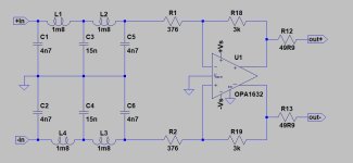
Here is a 5th order Butterworth adjusted to use available values for inductors and caps.
Inductors could be e.g. these:
https://www.mouser.fi/ProductDetail/Murata-Electronics/LQH43NH182J03L?qs=17u8i/zlE8%2BEHJV4Kc0uaQ==
This would be connected straight to summing resistors.
Inductors could be e.g. these:
https://www.mouser.fi/ProductDetail/Murata-Electronics/LQH43NH182J03L?qs=17u8i/zlE8%2BEHJV4Kc0uaQ==
This would be connected straight to summing resistors.
Attachments
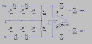
That’s interesting, but shouldn’t the 376R termination resistors not be connected to both OPA1632 inputs instead of to ground?Here is a 5th order Butterworth adjusted to use available values for inductors and caps.
Inductors could be e.g. these:
https://www.mouser.fi/ProductDetail/Murata-Electronics/LQH43NH182J03L?qs=17u8i/zlE8%2BEHJV4Kc0uaQ==
This would be connected straight to summing resistors.
But yes, that was what came out of the discussion with Marcel.
Hans
")
I’ll simulate this 5th order filter tomorrow.
I could not get the FM aliases with the original op-amp solution in my simulations, but I got the spectra around multiples of fs/2 that where causing these aliases.
It’s interesting to see how they got attenuated by different filters.
Hans
I could not get the FM aliases with the original op-amp solution in my simulations, but I got the spectra around multiples of fs/2 that where causing these aliases.
It’s interesting to see how they got attenuated by different filters.
Hans
I’ll simulate this 5th order filter tomorrow.
I could not get the FM aliases with the original op-amp solution in my simulations, but I got the spectra around multiples of fs/2 that where causing these aliases.
That's why I recommended sabotaging (*) the FIRDAC by doubling its clock frequency. Hopefully the intermodulation products the op-amp produces at audio frequencies are then big enough to be simulatable.
(*): in the sense of the word Mark doesn't agree with.
Thx, now I see clearly what you meant.
A picture sometimes tells more than a thousand words.
Hans
AK4493 applies a FIR filter (fc=156kHz) to DSD input data. This happens prior to switched capacitor dac. It is quite likely that this filtering makes all the difference.
It is possible.
I found that when listening to real DSD Files, rip's from commercials SACD's and processing only via FIR DAC, there was a strong tendency for "birdies" at low levels that were "unmeasurable".
I did not find them audible with DSD128 or DSD256 files originating from Merging Pyramix and Merging Hardware.
Passing the DSD signals through the simplest possible re-modulator (8 Tap FIR to 705.4/768k 32 Bit PCB and then re-modulating to DSD64 (all in FPGA) removed the birdies.
Thor
With normal 4-layer board having components on top layer the top plane is more of a pour and it becomes tricky to provide continuous impedance controlled plane for signal traces.
All design is a compromise.
Yes, they do cost quite a bit more. E.g. at JCLPCB Marcel's DAC board would be about 65 euros for 6-layers or 95 euros for 8-layers (5 pcbs) + shipping & taxes.
And presumably 45 Euro's for 4-Layer?
I generally deal with suppliers that are targeted at prototyping for commercial operations and I normally do not consider prototyping cost relevant, only mass production cost.
All that for uncertain (or at best slim) benefits.
That remains to be debated and tested. Have you read Ott's tome?
Thor
- Home
- Source & Line
- Digital Line Level
- Return-to-zero shift register FIRDAC