Hi Hans,
Just a few questions that might help to clear up the huge difference between your simulation and rather basic filter theory:
Could you post a picture of the schematic?
Is the summing node loaded by the 8.2 nF and the analogue filter?
Do you look single-ended or differential?
Are the rise and fall delays still unequal?
What other imperfections did you include?
What does it look like with an integer number of DFT sample points per clock period, with and without a Hann window?
Regards,
Marcel
1) To calibrate the 2x4 and 1x8 versions, I simulated a -60dB .dsf file and realized that the 1x8 version has a 6dB lower output level.
My posting in #2758 can therefore be disregarded, there is no real difference, the 6db difference in the image was because of this extra 6dB attenuation.
So, you were right, 1x8 brings hardly any benefit, but at least I found out the hard way
2) Then the question about the suppression.
The images with before and after the shiftregister were just meant as a relative ratio and not as an absolute one.
Point is that LTSpice works with 1Volt logic, where the real Firdac circuitry uses 5Volt, giving a level difference of 14dB.
But all shiftregister outputs, which are supplied with 4,5Volt, are multiplied with a VDVS with a gain of 4.5 to get the right voltages at the summation point of the 8 resistors.
So to get the absolute suppression value before and after, add 14dB and you will get the 55dB that you mentioned.
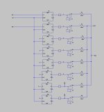
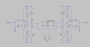
Rise and fall time are determined by the little squares in the sim with an equal 5nsec for both.
This added delay is needed because digital logic in LTSpice has no delay.
See first attachment with the building block for this part.
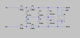
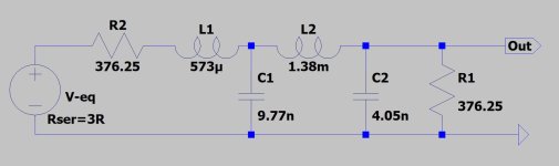
3) The summing point was loaded by a passive 4th order Butt. filter, see second attachment.
4) To get an integer number of DFT sample points, I could run a 16.772,216 msec window.
With 0.1nsec step time, that could possibly give 10 DFT sample points with a 16,277,216 FFT.
But the fact is that I don't know what steps LTSpice really takes, because the 0.1nsec step time only defines the maximum step time and not the real one.
If you want me to do this nevertheless, just give a confirmation and I can use several windows.
In this case I mostly prefer Blackmann-Harris.
Hans
My posting in #2758 can therefore be disregarded, there is no real difference, the 6db difference in the image was because of this extra 6dB attenuation.
So, you were right, 1x8 brings hardly any benefit, but at least I found out the hard way
2) Then the question about the suppression.
The images with before and after the shiftregister were just meant as a relative ratio and not as an absolute one.
Point is that LTSpice works with 1Volt logic, where the real Firdac circuitry uses 5Volt, giving a level difference of 14dB.
But all shiftregister outputs, which are supplied with 4,5Volt, are multiplied with a VDVS with a gain of 4.5 to get the right voltages at the summation point of the 8 resistors.
So to get the absolute suppression value before and after, add 14dB and you will get the 55dB that you mentioned.
Rise and fall time are determined by the little squares in the sim with an equal 5nsec for both.
This added delay is needed because digital logic in LTSpice has no delay.
See first attachment with the building block for this part.
3) The summing point was loaded by a passive 4th order Butt. filter, see second attachment.
4) To get an integer number of DFT sample points, I could run a 16.772,216 msec window.
With 0.1nsec step time, that could possibly give 10 DFT sample points with a 16,277,216 FFT.
But the fact is that I don't know what steps LTSpice really takes, because the 0.1nsec step time only defines the maximum step time and not the real one.
If you want me to do this nevertheless, just give a confirmation and I can use several windows.
In this case I mostly prefer Blackmann-Harris.
Hans
Attachments
I think 4) is unnecessary now, as you already have found the explanation. The loading by the filter won't have much impact at high frequencies, because the filter starts with an inductor (presumably an ideal one or an almost ideal one, that is, with LTSpice's default 1 mohm series resistance as its only imperfection).
Have a question about testing modulators which I broached in another thread at: https://www.diyaudio.com/community/threads/simple-dsd-modulator-for-dsc2.370177/post-7657022 Anyone have any related thoughts they would like to share?
Are you interested in a digital sigma-delta modulator by itself, combined with a DAC or combined with a coarse model of an imperfect DAC?
Regarding unusual tests:
You already mentioned offset sweeps. A variant of that is playing back a 1 Hz or 0.1 Hz sine wave, filtering it off at the DAC output and listening to the residue. It can reveal idle tone and nonstationary noise issues.
For just the modulator, on this forum, we had the Svitjod tests: compare the filtered output of a sigma-delta modulator with that of a linear time-invariant filter for some small and short duration signals, see https://www.diyaudio.com/community/...lta-dac-operation-wanted.311860/#post-5175695 It was meant for testing one specific hypothesis, no idea if it can be useful for anything else.
There are the subtractive tests with music: record the same signal left and right with a large difference in volume, make a weighted subtraction that should result in zero and listen to or measure what is left.
Introducing some intersymbol interference by making the weight of a bit depend on the previous bit is a simple way to check the effect that DAC imperfections could have on the output spectrum, like in post #2696. Does it just increase the noise floor or do you get peaks?
The latest PCM2DSD FW which "ignited" Markw4's question was aimed at improving issues found together with Marcel's RTZ dac. My understanding is that the latest modifications made to PCM2DSD FW are not altogether applicable to other DACs. But I don't see any problem with that. E.g. the developer of HQPlayer recommends specific type of modulators for ESS DACs and another type for AKM DACs.
Listened with an RTZ dac.
Also since my initial impression, I was able to get a 2nd opinion from another listener.
He and I agree on a few points:
1. Time domain dynamics of individual instruments and voices have been lost (in midi terminology we might say the ASDR envelope information has been diminished or lost; dynamics over time are flat).
2. L/R spatial positioning of voices/instruments between the speakers has been lost.
3. It sounds "bad." (maybe like lossy encoded)
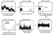
Regarding the first point, this seems like in principle it should be measurable as a change in the Analytic Function (Hilbert Transform).
Regarding the second point, as I suggested in the other thread (Simple DSD Converter...) its probably measurable in terms of inter-channel phase coherence and or ITD timing accuracy.
The above observations may be consistent with some of the list of unexpected audible effects described in Paul Frindle's AES paper on a professional digital mixing console:

Perhaps items (i), (b), and or (g) seem possibly related to what may have happened here?
EDIT:
Regarding the changes described by Bohrok2610 in the other thread (Simple DSD Converter...), seems to me like a change in dither might account for a lot. Don't know about the DC offset. Hard to imagine how increasing data length could be a bad thing.
EDIT 2: Some related information attached.
Also since my initial impression, I was able to get a 2nd opinion from another listener.
He and I agree on a few points:
1. Time domain dynamics of individual instruments and voices have been lost (in midi terminology we might say the ASDR envelope information has been diminished or lost; dynamics over time are flat).
2. L/R spatial positioning of voices/instruments between the speakers has been lost.
3. It sounds "bad." (maybe like lossy encoded)
Regarding the first point, this seems like in principle it should be measurable as a change in the Analytic Function (Hilbert Transform).
Regarding the second point, as I suggested in the other thread (Simple DSD Converter...) its probably measurable in terms of inter-channel phase coherence and or ITD timing accuracy.
The above observations may be consistent with some of the list of unexpected audible effects described in Paul Frindle's AES paper on a professional digital mixing console:
Perhaps items (i), (b), and or (g) seem possibly related to what may have happened here?
EDIT:
Regarding the changes described by Bohrok2610 in the other thread (Simple DSD Converter...), seems to me like a change in dither might account for a lot. Don't know about the DC offset. Hard to imagine how increasing data length could be a bad thing.
EDIT 2: Some related information attached.
Attachments
Last edited:
Hi Mark,
I have tried the V4 firmware ODDR2 variety on one of my Marcel RTZ dacs and am comparing with the V3 firmware on the other and I am not hearing what you report. I have to say that when A/B switching between them I can hear no obvious differences at all. My 2 DACs are as identical as I can get them in other respects.
Cheers,
Tony
Was it Marcel's RTZ dac? As I said the latest FW was tuned for that.Listened with an RTZ dac.
Hi Tony,
With all due respect, I have gone to great lengths to control all ground loops, shared impedance coupling, power supply optimization, SOA clocking, etc. with my dac. Much of it is based around Andrea Mori designed boards. Also the rest of the system is very high performance. One visitor who came here two times in the past when the dac wasn't as good as it is now described the sound in another thread: https://www.diyaudio.com/community/threads/dac-recommendation.376015/post-7560022
Don't know enough about your dac builds and overall system to make a comparison.
Cheers.
Mark
Last edited:
I'm sure most of us have gone to similar great lengths. How did you do the A/B comparison?With all due respect, I have gone to great lengths to control all ground loops, shared impedance coupling, power supply optimization, SOA clocking, etc. with my dac. Also the rest of the system is very high performance. One visitor who came here two times in the past when the dac wasn't as good as it is now described the sound in another thread: https://www.diyaudio.com/community/threads/dac-recommendation.376015/post-7560022
We have been through all this echoic memory stuff before.
https://www.diyaudio.com/community/threads/dac-recommendation.376015/post-7560632
https://www.diyaudio.com/community/threads/dac-recommendation.376015/post-7560717
https://www.diyaudio.com/community/threads/dac-recommendation.376015/post-7560730
https://www.diyaudio.com/community/threads/dac-recommendation.376015/post-7560789
Marcel,I think it's intermodulation between the tones around fs/2 that is apparently generated in the output filter, even though those tones are suppressed substantially by the FIRDAC and the 8.2 nF capacitors.
When you look at the spectrum plot with a simple single-bit sigma-delta and an offset in post #2696, you see a peak greater than 0 dB DSD around 2.8174 MHz. Its alias around 2.8274 MHz is equally large and the first op-amp stage in the filter has quite limited loop gain at such frequencies. Still, the intermodulation products bohrok2610 measured are only about -130 dB DSD.
The cosmetic flaw that allows intermodulation products slip into the audio band with certain DSD converters producing larger peaks around fs/ than others, are seemingly to be blamed to non ideal behaviour of the output filter, but Bohrok showed with his AK4493 D/A that those flaws can be fully suppressed with the right filter.
That made me make up my mind by attempting to design a more effective filter
The digital part of the RTZ FirDac however can be regarded as “almost blameless”
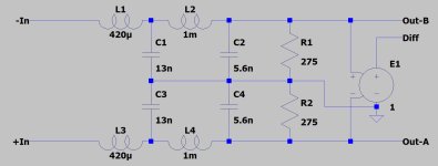
The Firdac’s register outputs are summed by eight 3k01 resistors. In a replacement diagram this can be seen as a voltage source driving a 376.25R resistor. This voltage source has an additional output resistance of ca. 4R.
You are talking about 8.2nF suppression, but when looking at the replacement diagram in the first attachment, you see a 2nd order MFB filter where the 8.2nF just is part of it, so because it is included in a feedback system, you can’t look at in isolation.
This first plus second MFB filter may not be any better as a passive 4th order filter tuned for 376.25R + 4R not having such 8.2nF cap, see the second attachment.
But in practice it can make a difference because Op-amp seem to have difficulties with the level of peaks around fs/2 and maybe even with large peaks at multiples of fs/2, resulting in unwanted aliases.
A passive filter may also have its flaws because of components behavior deviating as from certain frequencies from their nominal value.
But in general, the lower their nominal value, the higher the frequency where they start to deviate. This lead me to the following proposal for an alternative filter that’s more resistant to those HF peaks around fs/2.
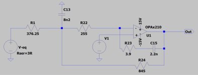
1) First start with a smaller cap of 1nF directly connected to the Firdac’s summing point, creating a pole at ca. 400kHz as a first line of defense to said spectral peaks around fs/2 and multiples.
2) Then followed by a discrete diamond buffer working in class A, with high BW and extremely low distortion. This buffer should drive a 4th order passive filter. In this buffer the low noise high BW Mat02 and Mat03 transistors were used, now replaced by the SSM2212 and SSM2220, but there are other alternatives to be found..
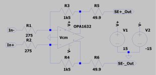
3) The passive 4th order filter is designed for a 275R impedance, where component values are still relatively easy to get or created from combining components in series or parallel and where the relatively filter low load results in a very low distortion for the buffer.
Here R1 and R2 are shown as the termination resistors, bur when using an amplifier behind the filter, these resistors will be replaced by the amps input resistors.
4) Finally an active differential op-amp to bring the output level at the usual 2Vrms for a 0dB audio signal and the DC level at zero Volt. This can be done with a OPA1632, where at this point al peaks have been removed from the signal.
The noise of this design including the eight 3k01 summing resistors gives a simulated equivalent input noise of 3.6nV/rtHz as opposed to the 13.6nV/rtHz for the original filter with OPA2210.
The Firdac delivers in the audio band a S/N of ca. 105dB at the summing point of the 8 resistors.
Zero dB at this summing point equals 0.375Vrms. That calculates for the equivalent voltage source into 2.1uV or 15nV/rtHz noise in the audio band. The added 0.3uV noise from the summing resistors can be neglected.
So, the proposed filter adds with 3.6nV/rtHz less than 0.25dB to the noise from the digital output.
Output from the buffer plus filter still has to be amplified by a factor 5.3 to get the usual 2Vrms for a Dac at the differential output.
Into the next posting I will show for different input signals the supposed effectiveness of suppression for peaks at fs/2 and its multiples.
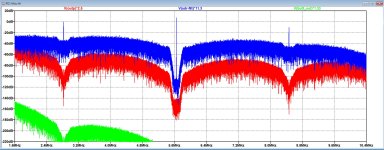
A first glimpse shows already a preview of part of the spectrum where the peaks are.
Blue is input signal to the Firdac's shiftregisters, Red is on the summing point with the 1nF cap and buffer connected and Green is at the output of the 4th order filter.
All levels are carefully adjusted and matched, giving absolute references levels, as will be shown in the next posting.
Hans
Attachments
Last edited:
- Home
- Source & Line
- Digital Line Level
- Return-to-zero shift register FIRDAC