scott wurcer said:
You are right PMA I figured 20-26 dB as line stage/headphone driver.
Hi Scott
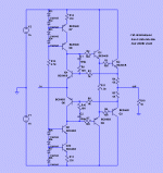
For line stages and headphone driver output buffer stages, that can be guaranteed to never leave class A, forget about things like diamond buffers and try this instead.
Run it in your simulator - you might be pleasantly surprised
Attachments
Oh, and here it is again in my no holds barred "open loop" line stage 


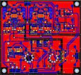
Build in dead bug form, PCB underway.....
Build in dead bug form, PCB underway.....
An externally hosted image should be here but it was not working when we last tested it.
G.Kleinschmidt said:Oh, and here it is again in my no holds barred "open loop" line stage

Build in dead bug form, PCB underway.....
Thank you Glen, simplicity at its finest. I'll start on one tomorrow.
G.Kleinschmidt said:
Hi Scott
For line stages and headphone driver output buffer stages, that can be guaranteed to never leave class A, forget about things like diamond buffers and try this instead.
Run it in your simulator - you might be pleasantly surprised
Great input impedance (post #62 ) - few M, I suppose ?
scott wurcer said:
Thank you Glen, simplicity at its finest. I'll start on one tomorrow.
In all seriousness that “Alison” class A buffer works extremely well. The two transistors acting to servo the bias current improve the linearity by well over an order of magnitude. The R & C’s around these two transistors make them operate as a pair of integrators, so the loop gain is accurately defined (ULG about 1.8MHz in that example I posted) and stability is assured. The –3db frequency of the buffer isn’t constrained by the ULGF either, which is nice.
juma said:
Great input impedance (post #62 ) - few M, I suppose ?
Many Megohms, but the input bias current is high (mismatch/tracking between the current sources used for biasing).
This means that you get an unmanageable offset voltage if you try to terminate the input to ground with a large (say 1M) resistor. This is why a preceded it with a tube buffer. 6DJ8’s are still in active manufacture, unlike so many JFET’s.
A 1M-ohm input resistor is nice, as you can then find a nice film input coupling capacitor that still fits onto a PCB.
G.Kleinschmidt said:Many Megohms, but the input bias current is high (mismatch/tracking between the current sources used for biasing)....
I was referring to sch in post #62 (common Base input stage)
juma said:
I was referring to sch in post #62 (common Base input stage)
So was I.
It has high input impedance despite being common-base because the negative feedback raises it. Ideally, the output voltage will be precisely equal to the input voltage, so Vbe of the input transistors is constant, and thus no change in input current is required with a change in input voltage.juma said:I was referring to sch in post #62 (common Base input stage)
I like Allison stages, too.
Glen, you might want to look at the ExtremA-thread (unless you haven't already), especially
http://www.diyaudio.com/forums/showthread.php?postid=1366820#post1366820
There I seem to have found (sims) a way to make it more useable for occasional(!) transitions into class-B, with a simple crossfeed add-on. Ignore the level shifter stuff (schottkys), though.
EDIT: Low-Z drive seems to be required to get low distortion with the standard allision.
- Klaus
G.Kleinschmidt said:
In all seriousness that “Alison” class A buffer works extremely well. The two transistors acting to servo the bias current improve the linearity by well over an order of magnitude. The R & C’s around these two transistors make them operate as a pair of integrators, so the loop gain is accurately defined (ULG about 1.8MHz in that example I posted) and stability is assured. The –3db frequency of the buffer isn’t constrained by the ULGF either, which is nice.
I was refering to the stacked 6DJ8's and associated biasing. Those Alison buffers look like the closed loop CF outputs we sometimes use with the input "flavors" switched. The bias gets a little hot for +-10V into 100 Ohm load.
G.Kleinschmidt said:So was I.
Right, it's just that when I saw you mention tube....
As far as DC offset is concerned I'd rather use servo (to CCS, not input) rather than tube buffer. Anyway, great circuit

KSTR said:I like Allison stages, too.
Glen, you might want to look at the ExtremA-thread (unless you haven't already), especially
http://www.diyaudio.com/forums/showthread.php?postid=1366820#post1366820
There I seem to have found (sims) a way to make it more useable for occasional(!) transitions into class-B, with a simple crossfeed add-on. Ignore the level shifter stuff (schottkys), though.
EDIT: Low-Z drive seems to be required to get low distortion with the standard allision.
- Klaus
Hi Klaus.
That thread is where I first saw it. I later stumbled across the original "Allison" reference describing it for a Class A power amp output stage.
To me it seems ideally suited for things like line-level and headphone driver stages.
scott wurcer said:
I was refering to the stacked 6DJ8's and associated biasing.
You know that bootstrapped 6DJ8 working as a cathode follower into the high input impedance of the Allison buffer generates such little distortion that you should be drooling.
I got the bootstrapped CF idea from a decades old Tektroincs publication on the theoretical aspects of vertical amplifier design. Built up the dead-bug prototype with a pair of 6DJ8's temporarily borrowed from the CH2 distributed amplifier of my Type 551 oscilloscope.
Ha, I knew it!G.Kleinschmidt said:That thread is where I first saw it. I later stumbled across the original "Allison" reference describing it for a Class A power amp output stage.
PMA said:OK, eagle sch is finished...
Well I've finished mine. Mr Wurcer seems to have taken a holiday from his discrete thingie.......
Attachments
PB2 said:I'd like to try some sims of this design, would people post their JFET models here if it is not too much trouble?
Has anyone compared them, are the models from Linear Systems the best?
Thanks, Pete B.
Hi Pete
I’m using the standard models in PSpice.
.model J2sk170 NJF(Beta=59.86m Rs=4.151 Rd=4.151 Betatce=-.5 Lambda=1.923m
+ Vto=-.5024 Vtotc=-2.5m Cgd=20p M=.3805 Pb=.4746 Fc=.5
+ Cgs=25.48p Isr=84.77p Nr=2 Is=8.477p N=1 Xti=3 Alpha=10u Vk=100
+ Kf=111.3E-18 Af=1)
.model J2sj74 PJF(Beta=92.12m Rs=7.748 Rd=7.748 Betatce=-.5 Lambda=4.464m
+ Vto=-.5428 Vtotc=-2.5m Cgd=85.67p M=.3246 Pb=.3905 Fc=.5
+ Cgs=78.27p Isr=129.8p Nr=2 Is=12.98p N=1 Xti=3 Alpha=10u Vk=100
+ Kf=26.64E-18 Af=1)
I think Pavel is using the same models that he used in the BT thread.
You will find some more info on Pavels site
here.
And on the BT thread here.
Cheers
- Status
- This old topic is closed. If you want to reopen this topic, contact a moderator using the "Report Post" button.
- Home
- Amplifiers
- Solid State
- Return of my differential VAS

