Hi,
Of course, it should be a stable R and not be impacted by whatever signal or current is sees during normal usage.
Far too many people consider passive components as being just Rs, Cs and Ls and that's where the links comes in as an eye opener for sure.
As the man from AD summed up (it's the only lecture from Uni I really remember in detail oddly) 'all components have extras (extra R, L and C). Be thankful you are not charged for them. But its always good to smile when you see someone sweating about a 3rd order effect to see that there are second and sometimes first order effects that they are completely ignoring. It also helps me keep my perspective.
You are right about radio. When I started out with HiFi there were zero radio sources in my listening room. I reckon I have 10 or more with me as I sit here now.
Indeed, RF interference has become a much bigger problem.
A switch turning off once an hour @ 10m, or a radio/TV station @ 30km are acceptable interference sources that can be easily attenuated.
But the half dozen or more RF transmitters @ <<20m and even on the same table top as our gear is not so easily attenuated nor tolerated.
We need to consider RF much more in our audio frequency designs.
In some cases the relevant period might not be zero crossing times but signal envelope times. If a tiny feedback resistor heated up too much during loud passages then the gain could vary. Avoiding this is just engineering.cbdb said:And for a music signal ( not a LF sine wave )the TC would probably be at least an order of magnitude higher. In other words, the temp. of a resistor dosnt change fast enough ( compared to the time between signal zero crossing ) to matter.
Most would, but sometimes it's worth looking at things from another angle. Analog Devices : Rarely Asked Questions (RAQs) : Resistors in Analog Circuitry (and apologies if this has been quoted before on this thread) contains bits of that late 80s lecture, but sadly missing the part about multiple resistors. Worth a scan to see how easily from a 'precision' standpoint you drop resolution.
Or we just accept that audio is not a precision discipline but some fun that allows us to sniff some solder fumes.
Yep #663, the target audience then was to busy attacking a Mod
")
I do sensitive analogue layout and have many times commented of design and good layout practice to take into account all the problems there are today with increased RF (often do designs that have to be able to handle up to 18GHz RF pollution), but often get shot down because the techniques dont fit with many audiophile views of layout... So now I don't bother...
As to resistors, on sensitive jobs the max voltage across any resistor is determined and the resistor is chosen so that it never goes over half its power rating, if an area is deemed very critical this de-rating factor may be increased to 3X.
Using SMD devices not only allows for smaller loop areas (especially in critical feedback loops) thus reducing the chance of picking RF up due to the decrease in effective dipole size, but also allows for using the layout to provide extra thermal management using copper shapes, planes etc under the devices.
Being this critical for layout is important as often the sensitive analogue sections have to work at a much wider temp range than commercial designs and failure is more problematic than just a bit of noise... But the same care for audio layout will put to bed many of the perceived demons and give a better design, but as said there seems to be a reluctance to look at the advice etc. as it is GOOD ENGINEERING PRACTICE and this seems incompatible with some on this site and their views of objective approach to design. Also there is a reluctance by many to embrace SMD design and thus get the benefits it gives, also the use of ground planes on sensitive low level (and power) designs, something that I have always done and seen on analogue designs for the last 30 years.....
Yep #663, the target audience then was to busy attacking a Mod
Not everyone bothers to actually read threads in which they participate, alas.
My resistance (so to speak) to SMD is purely practical- although Jan Didden showed me how to handle those parts, I still find it incredibly difficult from eye-hand considerations. These days, I even have to put on magnifying glasses to read the number codes off through-hole resistors.
I now have to put on reading glasses for everthing closer than infinity to see detail.
For electronics works I use 2.5 or 3.5 dioptres habitually.
Yet I still manage most smd resistorscapacitors down to 805 package easily using 3.5dioptres + a magnifier reading light. Yes, I need a lot of light and a lot of magnification to see the details. Fluorescent lighting and resistor colour codes are not fully compatible.
402 takes a lot more care, but I can still mange.
Why don't they label smd capacitors?
Resistors and semis get labels.
Oh. I do read the Thread posts !
Last edited:
For electronics works I use 2.5 or 3.5 dioptres habitually.
I have 2.0 and 4.0 glasses. I still haven't worked out a way to make my hands steadier (think of Gene Wilder in "Blazing Saddles").
That is the problem for DIYers, you do need extra equipment such as a magnifier and better soldering tools especially if you are going to change parts... I see people playing with 0201s and wonder how they do it, over 30 years in front of a computer, old age and high blood pressure has destroyed my once 20/10 vision, luckily when doing the layouts I can use the zoom function.
I have done a few layouts for people on here on the quiet and enjoy going back to playing with PTH designs (0.1" pitch based) its a trip down memory lane, and seems so easy now compared to modern designs.
It would be nice though to do a no holds barred design with SMD to see how small and integrated you could get a complete set up, DAC, filters, pre-amp etc in the same box and still please some audiophiles.
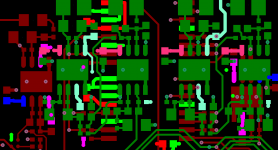
The pretty picture below (an audio design of sorts), the op-Amp packages pin pitch is 0.5mm, the vias 0.1mm laser drilled
I have done a few layouts for people on here on the quiet and enjoy going back to playing with PTH designs (0.1" pitch based) its a trip down memory lane, and seems so easy now compared to modern designs.
It would be nice though to do a no holds barred design with SMD to see how small and integrated you could get a complete set up, DAC, filters, pre-amp etc in the same box and still please some audiophiles.
The pretty picture below (an audio design of sorts), the op-Amp packages pin pitch is 0.5mm, the vias 0.1mm laser drilled
Attachments
Enjoy your sycophancy marce, you and DF96 should review the studies on stockholm syndrome.
There is no need to be rude, I may bring some irrelevance to my replies, but often do try and provide some useful information.
As to sychophancy, if you knew me you would know that I do not do that in any way, as DF96 and Andrew T (being from the UK) would understand, I am a gruff ruff dour cynical Yorkshire man from the Colne Valley, we don't do fancy or la de dah mate..... (Very near Last of the Summer wine country, same district different valley)
Oh. I do read the Thread posts !
I was not referring to you Andrew.
Alcohol.I still haven't worked out a way to make my hands steadier.
It would be nice though to do a no holds barred design with SMD to see how small and integrated you could get a complete set up, DAC, filters, pre-amp etc in the same box and still please some audiophiles.
The pretty picture below (an audio design of sorts), the op-Amp packages pin pitch is 0.5mm, the vias 0.1mm laser drilled
Yes, although BGA (which I have been told has advantages in some areas) are still spawn of satan in my mind, as they caused so much trouble back in the 90s then a whole lot more when lead free came in (XBOX red ring anyone...)
I would be of little practical use but would love to be involved with something like that. I'm currently building up a couple of the Modulus-86 Amps TomChr has designed and it has made me want a similarly objective DAC and pre-amp to go with it.
I have 2.0 and 4.0 glasses. I still haven't worked out a way to make my hands steadier (think of Gene Wilder in "Blazing Saddles").
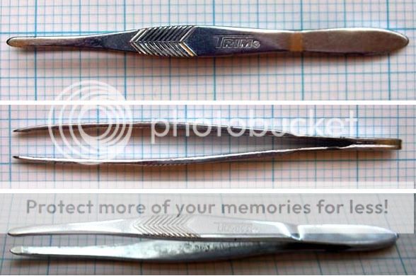
Avoiding caffeine goes a long way to steady hands. Plus, tweezers like these make things much easier.
http://www.widgetsupply.com/product/BEO60.html
Last edited:
Unfortunately, caffeine is my drug of choice.
Merlin's suggestion did work for Gene Wilder's character, but when following it, I seem to solder the wrong parts in the wrong places. rayma, Jan gave me a similar pair of tweezers and they transformed the job from impossible to merely difficult. I've been on the lookout for SMT vacuum tubes.
Ditto. I just get a bit annoyed when things I answered at the beginning of the thread are ignored in a wash of unfocused polemic from people who can't be troubled with reading. I try to be patient but do not always succeed.
Merlin's suggestion did work for Gene Wilder's character, but when following it, I seem to solder the wrong parts in the wrong places. rayma, Jan gave me a similar pair of tweezers and they transformed the job from impossible to merely difficult. I've been on the lookout for SMT vacuum tubes.
I may bring some irrelevance to my replies, but often do try and provide some useful information.
Ditto. I just get a bit annoyed when things I answered at the beginning of the thread are ignored in a wash of unfocused polemic from people who can't be troubled with reading. I try to be patient but do not always succeed.
Unfortunately, caffeine is my drug of choice.
Merlin's suggestion did work for Gene Wilder's character, but when following it, I seem to solder the wrong parts in the wrong places.
rayma, Jan gave me a similar pair of tweezers and they transformed the job from impossible to merely difficult. I've been on the lookout for SMT vacuum tubes.
For more complex boards with many parts, print enlarged photos of the pcb. Make one print for each value of part, and circle the parts with a single value on each photo. Install all the same value parts at one time using the guide, and then go on to the next value. This prevents installing the wrong value accidentally by keeping them separate, especially with unmarked capacitors. A stereo inspection microscope is a must if you do this often. Avoid smaller than 0805 if at all possible, though.
Last edited:
Incidentally, the best pair of tweezers I have ever owned are 'TRIM' blunt-tip tweezers. You can only get them in the US, AFAIK. I now have several pairs, the first from 30 years ago which are staggeringly fantastic for electronics work. But wouldn't you know it? They moved their manufactuering to China and the modern version, although they outwardly look the same, are not as good (but still better than any others I have found). And wouldn't you know it? The TRIM website seems to indicate the blunt-tips have been discontinued. Herblock's law.* Americans, if you happen to see them in Tigard or somewhere, buy up the old stock!Jan gave me a similar pair of tweezers and they transformed the job from impossible to merely difficult.
*If it's good, they'll stop making it.
- Status
- Not open for further replies.
- Home
- Member Areas
- The Lounge
- Resistor Sound Quality?