I assembled the Reflektor-D,I use it with I2S to PCM convertorBoard,very big step forward,more space,details,deep bass,very good power supply.
Start at 3,3 volts,after 30 minutes drop at 3,27 volts,how to raise the voltage a little?
Now another for the FIFO")
img67346 partagé sur ZimageZ
Thank Salas and Tea-bag.
Start at 3,3 volts,after 30 minutes drop at 3,27 volts,how to raise the voltage a little?
Now another for the FIFO
An externally hosted image should be here but it was not working when we last tested it.
img67346 partagé sur ZimageZ
Thank Salas and Tea-bag.
Congrats
Just little more RX value +15Ω or just little more Vf of green LED sample +0.03V (but does it really matter in your application?)
Thank Salas,I'll ask the question to Ian for the little drop.
in all cases it grows stronger
Network stuff then. Interesting.
Hi Salas,
Today I finally installed the RD for the Edel_NMR but something strange is happening...
The Edel is more than one month that is playing with no issue powered by a simple DIYINHK 3,3V that is the only VDD that the Edel need. The Edel have also 2 led to show what is the status :
Led 1 On / Led 2 On - Power Up - Booting.
Led 1 On / Led 2 Off - System Booted
Led 1 Off / Led 2 On - System Booted - Network is configured
Led 1 Off / Led 2 Off - An error occured
So, today I modify my DAC and power up with the RD. Everything fine and start to play music but after 2/3 minutes the Edel stop to playing. I measured the VDD and was 3.332V well in the limits of the 3.3V required. I noticed that the Led 1 and Led 2 was On (Power Up - Booting).
I shut down - restart and after a while I have the same behaviour. At the third time of the same issue I decide to dismantle the RD and to reinstall the DIYINHK.
Now is more than one hour that the Edel is playing with no issue so it is clear for me that the problem is caused by the RD but I have no idea which kind of issue should create all this.
I will appreciate your help or suggestions
Thanks and Regards,
Enrico
@ Enrico
Can't guess the Edel wants and hows, but in your shoes I would first be suspicious of possible max current demand bursts that are not allowed by the decided CCS setting on the new regulator. Could monitor with a DMM set on Min-Max function so to capture if a voltage drop happens when the system is halting. That would confirm current limiting. Obvious solution, smaller value CCS set resistor.
Can use the scope for that also if its not taking too long time to occur for observation patience to run out. That would give transient rail info on the incident too.
Can also bring the RX value on Reflektor bit down so to hit closer to 3.3V just in case some other peculiarity exists. Even twist the sense rail cables if long enough to pick some interference that gives weird trouble.
@ Enrico
Can't guess the Edel wants and hows, but in your shoes I would first be suspicious of possible max current demand bursts that are not allowed by the decided CCS setting on the new regulator. Could monitor with a DMM set on Min-Max function so to capture if a voltage drop happens when the system is halting. That would confirm current limiting. Obvious solution, smaller value CCS set resistor.
Can use the scope for that also if its not taking too long time to occur for observation patience to run out. That would give transient rail info on the incident too.
Can also bring the RX value on Reflektor bit down so to hit closer to 3.3V just in case some other peculiarity exists. Even twist the sense rail cables if long enough to pick some interference that gives weird trouble.
Thanks, I have the same though to take some measurement with the min-max function.
The twisting action is very easy to perform while for a scope I need to ask to a friend.
I will report back as soon I am done.
Cheers,
Enrico
The Reflektor I was collecting parts for is now heating up the sinks successfully... output is 1% higher than target at 3,30V after warm-up but I guess
my USB converter board won't mind.
I do notice that the IRF9610 sink is getting warmer than I thought with a 9V transformer.. can I safely step down to a 7,5 - 8V transformer to cut down on heat?
Mains voltage is pretty stable around here.
Great product btw.
Oh, and I forgot: CCS is set to 350mA with a 1R8 Isabellenhuette PBH, load was 27R.
Hi everybody
We are few of us that are wondering one very simple question.... regarding “implementation” of the different power supply....
I want to build an external case for them…holding the transformer and ?
few possibility :
xternal box that hold the power transformer ONLY
xternal box that hold the power transformer ONLY + the refectory D
connecting all this trough multiway cable to the "main box"...
We are talking here to power the buffaloIII and the sdTrans384 and some IV converter...
should “some” regulator be inside the same box (ie: not far)
does the “cable” that run the ppower could create “dirt” and unwanted noise ?
thanks for your input….
Phil
You can house transformer and rectification in external box so not to enter AC line in the main box. The Ref-D has DCin connector provision and local bypass cap place at the big capacitor's place. You just don't use the rectifying diodes and big capacitor locally on its PCB is the option. The regulator is better placed inside the main box closest possible to its client circuits loads.
Thanks for this clear answer.
Then bascally
Transformer AND rectification diode on xternal box and all the rest Inside the main chassis...
I have 6 refektor... Hope i can fit them inside the chassis...
Sorry to ask that.....
Analog section like digital section should be done like that ?
Or is there a absolute need for one or the other to be inside ?
In otherword everything that could be outside main box would arrange me))
But audio quality FIRST....
Tx Salas !
P
Then bascally
Transformer AND rectification diode on xternal box and all the rest Inside the main chassis...
I have 6 refektor... Hope i can fit them inside the chassis...
Sorry to ask that.....
Analog section like digital section should be done like that ?
Or is there a absolute need for one or the other to be inside ?
In otherword everything that could be outside main box would arrange me
))But audio quality FIRST....
Tx Salas !
P
Transformer, bridge, big filter capacitor in external box. Regulators inside main box with short wires to loads (twisted or shielded sense wires especially). That is the best for any regulator. When no room, all regulators can be in the second box with good care for sense lines. We don't want them to pick noise.
I (we have one more question regarding the Reflector D...
Then basically i will hold all the above in a separate case but now few other question raise....
Situation is the following :
We have 6 reflector D and maybe 2 placid HD BP together.....
1 -- is R-core better the toroidal ? does it make a HUGE difference ??
2-- we need 9volt transformer for the 6 reflector D
Since there are so many power reg sections, I understand it will be good to have one section per individual winding in the transformer, that is, not to share grounding.....
but could we have a double winding one ? 9V 0V 9V ?
should one use one single transformer for.digital with multiple ac.sections, say five to six...any drawback or capacitive couplings could make it.bad etc?
thanks for the advice !!
P
have one more question regarding the Reflector D...Then basically i will hold all the above in a separate case but now few other question raise....
Situation is the following :
We have 6 reflector D and maybe 2 placid HD BP together.....
1 -- is R-core better the toroidal ? does it make a HUGE difference ??
2-- we need 9volt transformer for the 6 reflector D
Since there are so many power reg sections, I understand it will be good to have one section per individual winding in the transformer, that is, not to share grounding.....
but could we have a double winding one ? 9V 0V 9V ?
should one use one single transformer for.digital with multiple ac.sections, say five to six...any drawback or capacitive couplings could make it.bad etc?
thanks for the advice !!
P
R-Core can be noticeably smoother due to better mains noise isolation, and casting a much smaller 50HZ alternating magnetic "shadow" to its surroundings.
Magnetically shielded toroid option with peripheral metal band is available from some manufacturers too.
You can use double or multiple 9V secondaries from one transformer. Its nearer to full separation, but not full. Still very good.
Magnetically shielded toroid option with peripheral metal band is available from some manufacturers too.
You can use double or multiple 9V secondaries from one transformer. Its nearer to full separation, but not full. Still very good.
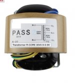
I have more more question regarding the power on the buffalo III with the reflektor
Does a power transformer like this one 30VA 9V/0V/9V would work ?
meaning having the buffalo III powered by a reflector D with 9V 15VA is enough ?
the buffalo draw about 440 ma i think....
i would power one one side the buffalo and on the other the SDTRANS...
thanks for the advice !!
Does a power transformer like this one 30VA 9V/0V/9V would work ?
meaning having the buffalo III powered by a reflector D with 9V 15VA is enough ?
the buffalo draw about 440 ma i think....
i would power one one side the buffalo and on the other the SDTRANS...
thanks for the advice !!
Attachments
- Home
- Amplifiers
- Power Supplies
- Reflektor-D builds