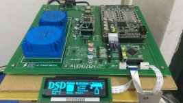
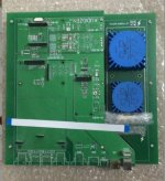
I'd say that the "lite" version is pretty much finished.
Perhaps if there is enough interest I could do a re-design specifically for the Soekris and do a small GB of PCBs.
I'm interested.
Hello guys!
I a writing for something that might have been said elsewhere. I tried byt did not find anything relevant I would be pleased if I had a brief reply.
I installed the latest filters, among which there exists the classic NOS filter. I have observed on the oscilloscope that the 10kHz and 20kHz sine waves (for 16/44.1 signal) do not appear to relate to classic NOS response. Judging from what I see on 16/44.1 signal, this module oversamples at least 4 times.
Is this true?
Is there a way to eliminate completely any oversampling process?
Thank you.
Peter
Cannot help you but have you tried looking (and maybe asking) in this thread?
http://www.diyaudio.com/forums/digital-line-level/269776-filter-brewing-soekris-r2r-136.html
http://www.diyaudio.com/forums/digital-line-level/269776-filter-brewing-soekris-r2r-136.html
Hello guys!
I a writing for something that might have been said elsewhere. I tried byt did not find anything relevant I would be pleased if I had a brief reply.
I installed the latest filters, among which there exists the classic NOS filter. I have observed on the oscilloscope that the 10kHz and 20kHz sine waves (for 16/44.1 signal) do not appear to relate to classic NOS response. Judging from what I see on 16/44.1 signal, this module oversamples at least 4 times.
Is this true?
Is there a way to eliminate completely any oversampling process?
Thank you.
Peter
If there were a Soekris DAM F.A.Q., this question would be damn near the top of it: http://www.diyaudio.com/forums/vend...magnitude-24-bit-384-khz-515.html#post4674073
DC Supply to DAM1021
Hi All,
My apology if this has been asked/answered elsewhere but I don't seen to be able to locate a definite answer so here goes:
Just got a DAM1021 board and is trying figure out the power supply to the board. This will be installed in an existing DAC so the only option available is +10VDC and -10VDC, i.e., AC not available. I planned to use two DEXA regulators to supply the DC.
Now according to the official doc the original AC inputs were passed through two diode bridges to provide the + & - DC outputs. However if the input supply GND (J1) also passes through diode as indicated by the doc then it will have a small potential difference (due to diode voltage drop) compared to the output GND. This normally won't be a problem if the source is AC but in my case the source is DC and the input GND is shared with the rest of the DAC which means when I connect the board's other GND connections (e.g., audio output) it will tie the board's GND to the input GND. This could result in a loop where current will flow because of the potential difference.
I tried measuring the input GND (J1) and the board's GND (screw hole) and it seems they are directly connected, i.e., not through a diode, so I am a bit confused here. And there appears to be only a single diode bridge (D2) near the supply input? How is the negative rail generated?
Wonder if anyone can shed some light on this? I try not to fry the board the first time powering it ...
Thanks!
That drawing is incorrect, there is only one diode bridge and you can just connect the +-10V as normal.
That drawing is incorrect, there is only one diode bridge and you can just connect the +-10V as normal.
Thanks to Søren for the quick reply. I'll proceed with the DC supplies.
Originally Posted by Dimdim View Post
I'd say that the "lite" version is pretty much finished.
Perhaps if there is enough interest I could do a re-design specifically for the Soekris and do a small GB of PCBs.
Hi
I am also interested
Cheers
P
Originally Posted by Dimdim View Post
I'd say that the "lite" version is pretty much finished.
Perhaps if there is enough interest I could do a re-design specifically for the Soekris and do a small GB of PCBs.
I'm interested.
I'm interested too.
OK guys, I've opened a GB for ArDAM Lite bare PCBs thread so we can stop "littering" here.
Thank you Soren for the hospitality. 🙂
Thank you Soren for the hospitality. 🙂
Like the old er layout better... more nice for tight spaces.. Will need very larger case for the last version?
Hi,
I got dam1021 rev3. I need to connect two tosliks inputs.
I got one toslink connected to SPDIF 2 (Toslink). It works.
Can I somehow connect second toslink to SPDIF 1 (Coax)? or SPDIF 1 (Coax) is only dedicated to Coax?
I got dam1021 rev3. I need to connect two tosliks inputs.
I got one toslink connected to SPDIF 2 (Toslink). It works.
Can I somehow connect second toslink to SPDIF 1 (Coax)? or SPDIF 1 (Coax) is only dedicated to Coax?
Last edited:
Hi,
I got dam1021 rev3. I need to connect two tosliks inputs.
I got one toslink connected to SPDIF 2 (Toslink). It works.
Can I somehow connect second toslink to SPDIF 1 (Coax)? or SPDIF 1 (Coax) is only dedicated to Coax?
A simple voltage divider (series resistor) from the Toslink receiver to the Coax input should do the trick....
When we design these considerations, a better sound is considered in this version. And can be easily split into 2 pieces, can become smaller.
View attachment 611398
Beautiful design. Looking forward to rev 4.
Beautiful design. Looking forward to rev 4.
Same here,
any progress with DAM1121 control?
- Home
- Vendor's Bazaar
- Reference DAC Module - Discrete R-2R Sign Magnitude 24 bit 384 KHz

