Hi,
I got my V2 couple of weeks ago and connected it to a DIYINHK XMOS (non isolated), Salas BIB +/- 12V, 3.3V Salas reflector-D and RPI2 with Runeaudio, DAMfilters, output to LDR>DCB1>Pass F6. Very pleased with the music produced by the set. Still waiting for he Nordmundss V2 companion boards to finish it.
Albert
The requested pics:
View attachment 515063
View attachment 515064
Looks like the mute circuitry has been changed...
Hi,Hi,
I got my V2 couple of weeks ago and connected it to a DIYINHK XMOS (non isolated), Salas BIB +/- 12V, 3.3V Salas reflector-D and RPI2 with Runeaudio, DAMfilters, output to LDR>DCB1>Pass F6. Very pleased with the music produced by the set. Still waiting for he Nordmundss V2 companion boards to finish it.
Albert
The requested pics:
View attachment 515063
View attachment 515064
Regarding the power supply feeds, may I know how did you do?
Did you just solder the +/-12V onto the PWD_IN? (AC input)
Or, did you solder it to J2 A+/A-?
How about the existing capacitors and rect bridge? Did you de-solder them?
For 3.3V, did you de-solder the 3.3V LDO and the capacitors around it?
How did you connect the power? To J2 3.3V or to the original 3.3V LDO Vout pin?
Thanks a lot.
Hi,
Regarding the power supply feeds, may I know how did you do?
Did you just solder the +/-12V onto the PWD_IN? (AC input)
Or, did you solder it to J2 A+/A-?
How about the existing capacitors and rect bridge? Did you de-solder them?
For 3.3V, did you de-solder the 3.3V LDO and the capacitors around it?
How did you connect the power? To J2 3.3V or to the original 3.3V LDO Vout pin?
Thanks a lot.
12V DC is connected to PWD_IN, caps and bridge untouched.
3.3VDC is connected to J3 3.3V ISO PWR IN and the XMOS device.
There is a Soekris DAM manual, however I could not find the download link right now, I have it downloaded. Take a look at the detailed hifiduino website for good guidelines.
Vref matching?
Hi, we have all seen that the Vrefs need to be matched at +- 4V. How would a 1mV mismatch or 100mV mismatch affect the performance? Should the Vref matching tolerance be the same as the resitor tolenace?
Would it be possible to test an external supply with +- 4V connected direct to the Vref caps(with the 5V regs removed) without removing the 4V regulators?
Ulf
Has anyone actually tried running dual mono dam's with the output inverter opamps bridged directly to balanced headphones? It would be nice if one could double the power output in this fashion by simply joining +/- on one side of the dam inverted outputs and the other half direct into one side of a set of cans.
EDIT: Bit the bullet on 2 new -12 boards as I been wanting to dabble with balanced mode.
EDIT: Bit the bullet on 2 new -12 boards as I been wanting to dabble with balanced mode.
Have anyone did 16 caps mod to new v2 soekris? what change in sound?
The 16 cap mod isn't necessary anymore. On a v2 board adding a single 1500uF 6.3V 10mohm polymer cap and swapping/bridging the 499R (Rp) resistor with 50R should obtain better results which is what I plan on doing for my next build upgrade. Unfortunately much good information continues to get lost in this thread unless one digs it up.
Last edited:
Hi, we have all seen that the Vrefs need to be matched at +- 4V. How would a 1mV mismatch or 100mV mismatch affect the performance? Should the Vref matching tolerance be the same as the resitor tolenace?
Would it be possible to test an external supply with +- 4V connected direct to the Vref caps(with the 5V regs removed) without removing the 4V regulators?
Ulf
Ulf, please see the implementation thread recent posts for some comments by soren about this.
http://www.diyaudio.com/forums/digi...ris-s-dac-implementations-80.html#post4505364
Last edited:
Thanks wineds.
OK so it is quite critical with the Vref balance. Would it be possible to measure the DC offset on the output, playing silence, to balance the Vref?
Ulf
That's a very interesting idea ulf. Maybe. But perhaps vref unbalance only determines the magnitude of the positive and negative excursions?
Last edited:
OK Wineds, your probablu right. So a spectrum analyzer and adjusting for minimum distorsion should be better to set the balance.
Do you think I would fry the components if I apply +-V with the Vref regulators in place? It would be nice to be able to test this without too much scary SMD soldering.
I have a nice BP superregulator (JSR-06) that I am curious to try. I have also added a fine tuning Pot for the balance to this supply that allows me to set the symmetry.
Ulf
But Yours mod have not been testes, 16 caps mod have been testes by couple peple, my friend told me that change it sound is amaizing, but he has v1 soekris. Have any one testes mod with one cap and 50R resistor? by the way where this resistor on pcb is?The 16 cap mod isn't necessary anymore. On a v2 board adding a single 1500uF 6.3V 10mohm polymer cap and swapping/bridging the 499R (Rp) resistor with 50R should obtain better results which is what I plan on doing for my next build upgrade. Unfortunately much good information continues to get lost in this thread unless one digs it up.
If I want to use my own, discrete buffer (DCB1) for the raw output, what value of input impedance should I be aiming for? The opamp buffer/unbal-bal stage that's on the board doesn't seem to have any resistive loading according to the schematic from https://hifiduino.wordpress.com/2015/01/30/building-soekris-r-2r-dac/
OK Wineds, your probablu right. So a spectrum analyzer and adjusting for minimum distorsion should be better to set the balance.
Do you think I would fry the components if I apply +-V with the Vref regulators in place? It would be nice to be able to test this without too much scary SMD soldering.
I have a nice BP superregulator (JSR-06) that I am curious to try. I have also added a fine tuning Pot for the balance to this supply that allows me to set the symmetry.
Ulf
Ulf, have a look at moreDAMfilters
There are many articles about vref modding. It looks like the end result can be made very good in terms of ripple.
The current vref configuration has 4 buffers. One for each shift register row. This means separate vref for each channel. I think this has advantages compared to using one vref supply for both channels.
If you must, to disconnect the existing vref supplies you would need to remove at least the series resistor and the sense resistor. But then you would need to verify the exiting vref buffers are not oscillating - so in the end you may also have to remove the 4 vref OPAMPS. I don't think it is worth it to go down this path.
I'm looking for a NOS filter (with the correct De-emphasize setting) that works in ver. 0.99 firmware because I desperately need one.
Need it to test the 16 caps mod I just made.
Okay, found it myself over on moredamfilters. Of course Paul included one in his The v099 Party Pak
“Bank 4: NewNos. Yes, that one….”
It's posible a new improvement: 0.1 / 560/10 4x4700 0012 ESR. Zout have 3 mOhm.
PCG0J272MCL1GS Nichicon | Mouser
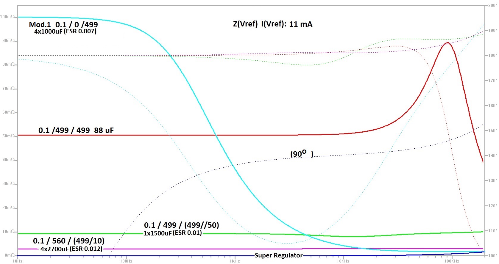
We made comparison between: [Mod.1 0.1 / 0/499 4x1000uF 0.007ESR] and [0.1 / 560/56 1x1500 0.01 ESR]. It leaves doubt.
Comparisons have made with two DAM1021. Both sound great, beter than other DACs I have. And better than original 0.02 DAM1021 Ver.1.
Surprises, we have listening clear differences between the two configurations.
The new 1x1500 uF have analog sounds, very natural.
Mod.1 version is most spectacular scene, detail and dynamics. I prefer it. Have slight imbalance between bass and treble in that. But perception of this difference is more similar to the graph of impedance variation in the current. Mod.1 is better with less impedance variation.
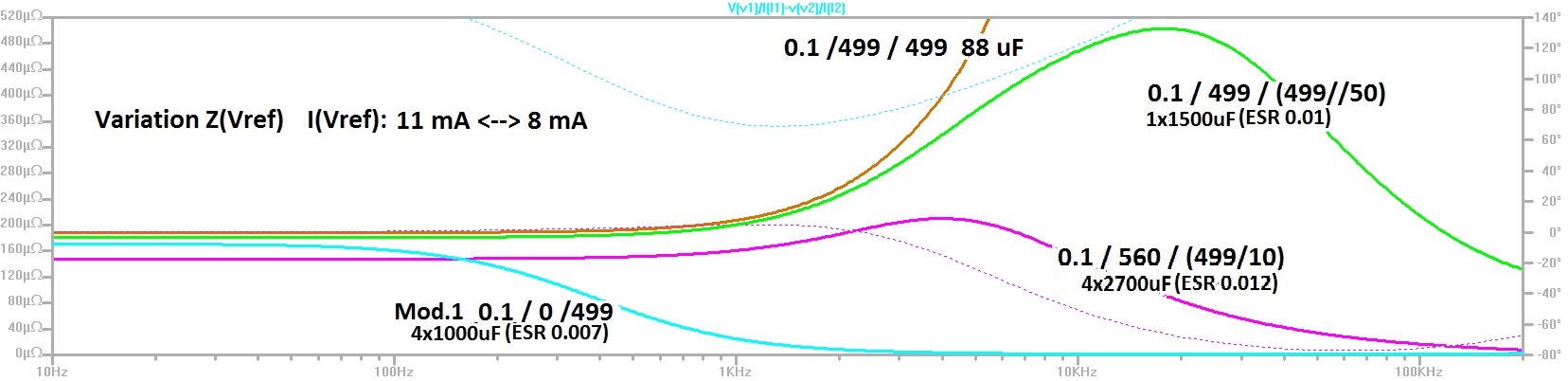
I think DAM1021 can give in bass more detail and dynamic. I think 4x2700 uF and 3 mOhm not going to make a big improvement in that. Have low impedance but no bether variation with the current than mod.1.
PCG0J272MCL1GS Nichicon | Mouser
We made comparison between: [Mod.1 0.1 / 0/499 4x1000uF 0.007ESR] and [0.1 / 560/56 1x1500 0.01 ESR]. It leaves doubt.
Comparisons have made with two DAM1021. Both sound great, beter than other DACs I have. And better than original 0.02 DAM1021 Ver.1.
Surprises, we have listening clear differences between the two configurations.
The new 1x1500 uF have analog sounds, very natural.
Mod.1 version is most spectacular scene, detail and dynamics. I prefer it. Have slight imbalance between bass and treble in that. But perception of this difference is more similar to the graph of impedance variation in the current. Mod.1 is better with less impedance variation.
I think DAM1021 can give in bass more detail and dynamic. I think 4x2700 uF and 3 mOhm not going to make a big improvement in that. Have low impedance but no bether variation with the current than mod.1.
Attachments
- Home
- Vendor's Bazaar
- Reference DAC Module - Discrete R-2R Sign Magnitude 24 bit 384 KHz