This looks pretty nice. It should work just fine.
I myself will wait for Soren's new firmware that will support isolated serial connection.
But beware: the isolated serial port will be TTL and so only capable of "talking" to TTL devices (a.k.a. little 2$ USB to Serial converters). Plus, though it will be isolated from the DAM, it will not be isolated from the USB to I2S interface board since they will share a common ground.
The volume pin doesn't do anything at all, even shorted to ground at powering on, it sets to V+00. The pot I'm using is just a cheap 10K job, but it tested linear, scaling from 0V to 3.3V from min to max. Nothing happens however, connected or not, nor disconnected while powered on, volume stays at V+00.
Must set V-99 for the pot to work
Has Soren documented what voltage SHOULD be at the VOLUME_POT pin for V-99? I can't get it to do anything from anything from 0 to 3.3V.
Has Soren documented what voltage SHOULD be at the VOLUME_POT pin for V-99? I can't get it to do anything from anything from 0 to 3.3V.
I think not. Its probably fairly linear with rotation. There is a bit of information here but not sure if it helps :
https://hifiduino.wordpress.com/2015/03/16/soekris-dam-1021-r-2r-dac-users-guide/
I think not. Its probably fairly linear with rotation. There is a bit of information here but not sure if it helps :
https://hifiduino.wordpress.com/2015/03/16/soekris-dam-1021-r-2r-dac-users-guide/
Anyhow this is why I'm thinking these input pins are dead/inoperable. When shorting either of the input select pins to ground while no inputs are connected you should see the serial output display the selections, which it does for only one of the input pins. I don't believe they have ever worked on my unit as I only tried recently.
Is it possible to connect directly from CDPro2's I2S output to Soekris Dam1021?
I don't see why not. I have one ordered myself for that application. I will report once it's setup in the implementation thread.
Is it possible to connect directly from CDPro2's I2S output to Soekris Dam1021?
I believe it depends on which I2S connection you are using.
As there are many different connection method available from different vendors.
The volume pin doesn't do anything at all, even shorted to ground at powering on, it sets to V+00. The pot I'm using is just a cheap 10K job, but it tested linear, scaling from 0V to 3.3V from min to max. Nothing happens however, connected or not, nor disconnected while powered on, volume stays at V+00.
Did you try glt's suggestion of using the serial interface to set V -99?
Some time ago I managed to brick the volume pot and remembered an early post from Soren indicating the need to reset the pot by entering V -99. It worked.
Did you try glt's suggestion of using the serial interface to set V -99?
Some time ago I managed to brick the volume pot and remembered an early post from Soren indicating the need to reset the pot by entering V -99. It worked.
I set V-99 in the serial console multiple times (tried with all various positions of the pot), which mutes the volume, however the pot does not respond at all. I've tried another pot to no avail. Directly wired the pot to the board (bypassing the input board), nothing. What exactly does setting the volume to V-99 do anyway to reset the pot? Nothing is stored in firmware is it not? Anyhow its like the system doesn't even see the pot, on startup volume is always V+00 as if it weren't even connected. I even went as far as to check the continuity between the input pins and the actual microcontroller *pins* on the board, which all checks out.
Last edited:
I set V-99 in the serial console multiple times (tried with all various positions of the pot), which mutes the volume, however the pot does not respond at all. I've tried another pot to no avail. Directly wired the pot to the board (bypassing the input board), nothing. What exactly does setting the volume to V-99 do anyway to reset the pot? Nothing is stored in firmware is it not? Anyhow its like the system doesn't even see the pot, on startup volume is always V+00 as if it weren't even connected. I even went as far as to check the continuity between the input pins and the actual microcontroller *pins* on the board, which all checks out.
Odd. Have you tried re-installing the firmware?
Suspect the V-99 resets a baseline in the firmware for reference. From everything you've said I'd guess you either have corrupt firmware or a hardware issue. With luck a firmware re-install will deal with the former.
I set V-99 in the serial console multiple times (tried with all various positions of the pot), which mutes the volume, however the pot does not respond at all. I've tried another pot to no avail. Directly wired the pot to the board (bypassing the input board), nothing. What exactly does setting the volume to V-99 do anyway to reset the pot? Nothing is stored in firmware is it not? Anyhow its like the system doesn't even see the pot, on startup volume is always V+00 as if it weren't even connected. I even went as far as to check the continuity between the input pins and the actual microcontroller *pins* on the board, which all checks out.
Maybe you could try reflashing the firmware? And possibly stock filter?
Hey guys,
I am not a big fan of LDOs, so I am thinking of remove all LDOs(+-5v, 1.2v, 3.3v) from dom1021 board and supply power with each voltages with discrete power supplies. Soekris mentioned that it is not recommended, but I think it might improve the sound.
Some will be very difficult to solder wire on board due to very tinny soldering surface; however, it will be clearly done if I use J2 Pins. The problem is I don't know J2 patterns can hold powers.
any opinions?
Hey guys,
I am not a big fan of LDOs, so I am thinking of remove all LDOs(+-5v, 1.2v, 3.3v) from dom1021 board and supply power with each voltages with discrete power supplies. Soekris mentioned that it is not recommended, but I think it might improve the sound.
Some will be very difficult to solder wire on board due to very tinny soldering surface; however, it will be clearly done if I use J2 Pins. The problem is I don't know J2 patterns can hold powers.
any opinions?
There are also LDOs (very samll) after J2 so you have to replace all LDOs with new sources if you want to achieve any progress..
There are also LDOs (very samll) after J2 so you have to replace all LDOs with new sources if you want to achieve any progress..
here is a picture from link.
What I can see from the board is very small switching 1.2v regulator at capacitor rails, 3.3v LDO at clock, +-5v LDOs. Please let me know if I miss.. 🙄
remove those four LDOs and supply each voltages via J2 pins, will it be okay?
Attachments
If you read more of the posts you would see this has been discussed many times.
J2 are power outputs. If you power from there it will not do what you want. In addition, the power will be too far away from its intended target. So you gain nothing since nothing is more useless than a reg not in intimate contact with its circuit.
SOEKRIS has assured the chances of destroying the board are far greater than any chance of success. It is not that he wants to discourage experimentation.
You can replace the 3.3 reg that powers the clock but to go further one should be ready to purchase another board. nige2000 has done this but he also eventually destroyed his board attempting to go further and I am not aware of anyone with more experience at doing such work. nige2000 is using a float charged battery setup there
AS one initially brimming with fire to modify this board I have been tempered by the sound of the thing as it is. Of course, improving the primary supply is worthwhile. Replacing the caps after the power input is worthwhile. But as with any component, let it run for a good while before making any assumptions about how it sounds.
Using the boards output before the balanced output stage is mandatory for best sound.
spzzzzkt's filters are a far more important step than messing around beyond the simple and obvious places where cost affected design decisions. To attempt to replace the regs that supply the resistor ladders could be very disappointing if one does have a ready back up. (nothing to listen to)
One does have to consider, which I readily admit took me awhile to understand, that SOEKRIS did a very fine job of balancing compromises in the design of this board. It is a great value.
It would be interesting if he decided to do a run of cost no object boards and incorporate the things many of us are curious about but in the interim the thing sounds damned good and will keep me satisfied until the next step arrives.
Even if there is not such a "next step" I do not think one can come close to what this thing can do without spending a great deal more money.
Detail and information are important to me more than a lush tonal balance and this is why I am enjoying this thing so much. For those whose tastes differ you might not ever find true happiness with this board and I do not think changing regulators will change the basic character of this DAC.
Wasn't aware there was a layout difference between the .05 boards and the 0.02/0.01 boards. The image in post 2595 above is from glt's site and I believe he has a 0.05 board. J3 in the image above is a 16-pin header as against the 26-pin header of the .01/.02 boards I've seen so far.
Or has Soren introduced a redesigned board?
Or has Soren introduced a redesigned board?
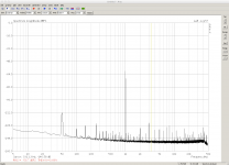
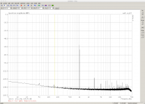
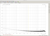
Coming back to the noise via the serial connection. I notice some 50Hz and harmonics enter the signal when the serial connection (via USB adapter) is attached. The music signal is supplied by USB from a laptop. If the laptop power supply is attached or not has no influence, but there are several other items connected to the laptop which are powered by AC power.
-60dB 1kHz with serial connection

-60dB 1kHz without serial connection

noise floor

-60dB 1kHz with serial connection

-60dB 1kHz without serial connection

noise floor

Or was it an early image of a pre-production prototype?
Søren changed the layout for the production boards. The photos posted on Soekris Engineering, Inc. | products dam1021 show the prototype layout. The pics on glt's site show the production layout: https://hifiduino.wordpress.com/2015/01/30/building-soekris-r-2r-dac/
- Home
- Vendor's Bazaar
- Reference DAC Module - Discrete R-2R Sign Magnitude 24 bit 384 KHz
