Diyengineer,
My head is spinning, yours must be too...
As we have said before there are 2 faults. (They may or may not be the same problem.)
Why not park the chassis/transformer/choke buzz for a while and reflect on the speaker hum a while.
Easy to try this one:
I have been re-reading from the start and something right back in post #10 is odd.
Refering to your grounding scheme, ''A single wire from the input jack is connected to chassis ground through an X2 cap attached to the filtered IEC inlet.'' So what happens if you ground the jack to the chassis directly ? Its more normal to have a direct connection or low value (10 ohms ish) resistor there.
Then do the removing the tube test to see which stage is the problem as Hooman says?
Hooman, you could be right - more experts always welcome, but they will only ask the same questions and wait for the answers.
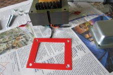
OK, all this reminded me a similar situation I've faced so I checked the photo in post #51. I can't be sure but if the yellow wires going to the rectifiers are coming from the transformer then I think the rectifiers are connected the opposite polarity(?) Could you please check that?
The transformer is 2x350V/200mA. This is not what I had in mind when I said it's small. I was corrected in previous posts and I agree, don't spend more money in iron, it's something else.
The transformer is 2x350V/200mA. This is not what I had in mind when I said it's small. I was corrected in previous posts and I agree, don't spend more money in iron, it's something else.
Diyengineer,
My head is spinning, yours must be too...
As we have said before there are 2 faults. (They may or may not be the same problem.)
Why not park the chassis/transformer/choke buzz for a while and reflect on the speaker hum a while.
Easy to try this one:
I have been re-reading from the start and something right back in post #10 is odd.
Refering to your grounding scheme, ''A single wire from the input jack is connected to chassis ground through an X2 cap attached to the filtered IEC inlet.'' So what happens if you ground the jack to the chassis directly ? Its more normal to have a direct connection or low value (10 ohms ish) resistor there.
Then do the removing the tube test to see which stage is the problem as Hooman says?
Hooman, you could be right - more experts always welcome, but they will only ask the same questions and wait for the answers.
yes this kind of questions are complete normal and help to fix problem .
but why not success?
there is bad grund in this hand made amp .sorry for this !but 8 years before i conect 96 db speaker to my hand made se amp .hum

every ting was good as schematic .but ground was different to original amp.
so i tray with gerund in resistor of first tube.in 15 min...my amp receive to optimum ground and be quit as amp is off.
we have more way for solution but one of them is excellent .
no need to put big cap or big filter in power supply.no need to big battery
after 100 post we don't know abut source of hum in speaker .
first stage ?
phase split ?
power section ?
please help us to know .
Hi all,
Yes, this is definitely confusing. I'll run through the questions with some answers.
"Increased buzzing- was it from the trans or new choke"---- It is really hard to tell, especially since the tone of the buzz went slightly lower. I did experiment with mounting positions also to see if it was coupling with something. Also, I can feel absolutely no vibrations anywhere on the amps, I know from reading other posts that sometimes these mechanical buzzing can be felt.
6A3s, The chassis is non-magnetic stainless.
I do have four 1uF 630V caps on hand, I can try the caps later today before the choke.
Yes I bought the Hammond Reactor 193H, 5H 200mA. It arrived in its sealed box and did not look dropped at all.
The power trans' were not dropped. Aside from painting the outside of the bells, no other disturbances. and I made sure that both bell covers are grounded to the chassis.
Alan, As far as my grounding scheme, I re-wired it per 6a3s' #88 post. While I'm sure the amps are grounded better now, it made no audible difference. I forgot to mention that there is also a low value resistor across that cap. I have also tried going right to the chassis with no difference.
I have pulled the tubes one by one before but forget my results. I will do this again today and report back.
MagicBus, The yellow wires are the 5V taps going to a diode bridge to power the led in the lighted power switch. In troubleshooting, I have disconnected these taps to see if it was causing the buzz but no luck.
hooman, You stated "so I tray with gerund in resistor of first tube". Could you clarify this? Do you mean "resistor in ground of first tube"?
I will pull tubes one by one later today and let you know.
Thanks guys!
Hi all,
hooman, You stated "so I tray with gerund in resistor of first tube". Could you clarify this? Do you mean "resistor in ground of first tube"?
I will pull tubes one by one later today and let you know.
Thanks guys!
thanks ...hum bad reason of ac .some circuit work with battery and no need to find way for hum
some times i worked 2 0r 3 days for hum . special in guitar amp .
..
1- we can start from end to first of amp circuit .
2-please short g1 of all 4 power output tubes to ground. if hum stop in speaker ..please change output circuit to normal and coutinho ...3-remove cap .22mf frome pin 6 of ef86... if hum stop ... first stage makes this hum .
it t is common test in trouble shooting hum in push pull amps.
I don't think you want to ground both end bells. You should also revisit the transformer bolts. Read this with special attention to paragraph one and four.
http://www.hammondpowersolutions.com/files/HPS_article_Core_Construction_Basics.pdf
http://www.hammondpowersolutions.com/files/HPS_article_Core_Construction_Basics.pdf
Did you disassemble the transformer to paint bells? Did you tighten nuts well?
Did you put back insulation washers and pipes on bolts?
It can be the result of a shorted turn through bolts and bells.
It could be free rattling bobbin on an iron.
It can be rattling turns in the bobbin.
It can be magneto-striction due to saturation on peaks, if the transformer was designed for slightly lower voltage than you have. You can check it by a variac.
The Hammond 200 series transformers just seem to be using flat insulating washers. The 300 series and the Edcors are using nylon shoulder washers to make sure the bolt is centered in the lamination hole as well. I don't know how important the centering is but I switched my Hammond 278CX transformers from the stock flat washers over to the nylon shoulder washers as part of my buzz reduction quest on them. They are notorious for buzzing and I have them quieter than my filament transformers now. Was it the shoulder washers? Don't know but I don't think the transformer manufactures would use them if they did not have some purpose and they are cheap.
Digikey number for #8 bolts:
Electronic Components and Parts Search | DigiKey Electronics
Digikey number for #8 bolts:
Electronic Components and Parts Search | DigiKey Electronics
Hi Diyengineer,
Can we cross another thing off the speaker hum list please?
Way back in post #15 you said, ''The changes I made such as the NFB and the gain control had a positive impact on the sound quality.''
There was no NFB in the original, you added the 330 / 22k ohm / 470pF scheme. What happens to the speaker hum if you remove the blue wire from the speaker socket? I know the gain will go up and general noise - but is the speaker buzz the same, better or worse?
Out of interest how did you derive those values?
Alan
Attachments
Hi Alan,
Both the buzz and general noise decreased for sure when using the NFB. I know from reading a lot of forums that a lot of people’s designs don’t use NFB or very little. This design benefitted a great deal. Plus the decrease in gain helped a lot.
I got the values from looking at different schematics for samples. The 330R and 1.2k add up to the original 1.5k to keep those cathode currents the same. I tried a few different combinations. Then I used a pot in place of the 22k and tried a couple different caps. I adjusted the pot for lowest noise and best overall sound.
For learning purposes, how would you have done it?
Thanks
- Status
- This old topic is closed. If you want to reopen this topic, contact a moderator using the "Report Post" button.
- Home
- Amplifiers
- Tubes / Valves
- Reducing gain in a monoblock