Hello all,
My findings:
1. Insulated endbells from EI frames and all bolts of all transformers. All was verified with a meter. No change in buzz.
Hooman: per your post#106,
1. I shorted g1 of the power tubes to ground and it made a horrible screeching noise.
2. I disconnected the .22 coupling cap from the EF86 and the buzz got much louder.
3. I pulled the power tubes and the amp went silent.
4. I pulled the driver and the mechanical hum stayed the same but the hum in the speakers was greatly reduced. I have tried other driver tubes previously and the buzz stayed the same.
I’m not sure if it would be worth trying or not but possibly mounting the .047 coupling caps point to point to the g1’s. Right now they’re on the board. Not sure if there’s any stray inductence from the wires. They’re pretty short though.
Thanks guys
I got the values from looking at different schematics for samples. The 330R and 1.2k add up to the original 1.5k to keep those cathode currents the same. I tried a few different combinations. Then I used a pot in place of the 22k and tried a couple different caps. I adjusted the pot for lowest noise and best overall sound.
For learning purposes, how would you have done it?
Without a scope, signal generator and dummy load, just like you - trial and error and hope.
It is actually quite difficult to calculate in a simple way as there are several variables that each needs its own rather complicated maths. (It was slide rules and tables when I did it last.)
I cannot find a simple 'guide' online, so that tells you something. Maybe another poster can point us in the right direction?

Without a scope, signal generator and dummy load, just like you - trial and error and hope.
?
this tools just use for monitoring .
Last edited:
Now I’m even more confused.
I disconnected those .047 coupling caps at the two marked locations. Mechanical buzz and speaker buzz stayed exactly the same. For Some reason I tried to play music, I could still hear music from the tweeter with the coupling cap disconnected. Not sure how this is possible?
Nevertheless, the buzz was unchanged. But when the driver tube is pulled, the buzz over the loudspeaker stops.
Don’t know what to make of this.
Thanks a lot
Last edited:
Without a scope, signal generator and dummy load, just like you - trial and error and hope.
It is actually quite difficult to calculate in a simple way as there are several variables that each needs its own rather complicated maths. (It was slide rules and tables when I did it last.)
I cannot find a simple 'guide' online, so that tells you something. Maybe another poster can point us in the right direction?
I do have a scope and a dummy load but no signal generator. My problem with the scope is I can read and operate it, im just not sure what to check in certain conditions and what readings would be good or bad.
I did use it to track down 120hZ hum before, so it was useful then
...I could still hear music from the tweeter with the coupling cap disconnected....
There is capacitance EVERYWHERE.
A number I use in general work is 30pFd to ground at every node. From one node to another will be less, depending on the geometry.
The 0.047u passed "full bass". 20pFd (0.000,020uFd) will pass less bass. The bass cutoff goes up about 2,000:1. Assuming stock bass is 10Hz, the new bass limit is 20,000Hz. And with a soft roll-off. I'm sure that, turned-up, there would be audible tweet.
Just my 2 cents....
I once wanted to convert a Philips Pa amp (mono, 4xEL34,750-800V Ua, pentode conn.,150W output).
I did not need so much power and wanted to improve the sound.
So I connected the tubes as triodes and used chocke input.
To my suprise the powertransformer started to buzz.
There was no cure for it other than to use half-bridge driven cap input (with comparable low value caps) instead of the
original fullbridge.
L input produced considerable MORE electromechanical buzz than C input!
Last edited:
There are some transformers that buzz even under no-load conditions.
A series resonant choke and capacitor that lands on the same frequency as the ripple (not often likely) is a dead short (actually a very low impedance, given the DCR of the choke, and the dissipation of the cap).
A choke input power supply that has a choke that does not have at least critical inductance, is not really a choke input power supply.
I do have a scope and a dummy load but no signal generator. My problem with the scope is I can read and operate it, im just not sure what to check in certain conditions and what readings would be good or bad.
I did use it to track down 120hZ hum before, so it was useful then
Time to practice again then. Why not start by connecting it to the output (with the dummy load connected) and seeing what waveform the buzz is? Make a shorting plug for the input jack so there is no input signal.
Time to practice again then. Why not start by connecting it to the output (with the dummy load connected) and seeing what waveform the buzz is? Make a shorting plug for the input jack so there is no input signal.
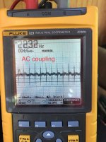
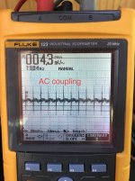
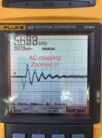
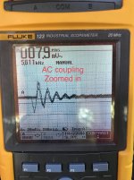
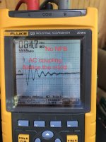
Here are some readings taken at the 4R tap when warmed up, with a 4R dummy load and the input grounded.
The dark horizontal likes are dead pixels. My scope needs a new screen.
Hooman, see post #125
Thanks
Attachments
Last edited:
I understand why you say Buzz and not Hum now.
What I do not understand is how to describe the traces other than 'ringing'. Is it 20 -22 Hz or 5.6kHz ringing?
I guess there is something oscillating and sorry to go this way again, but most likely is the NFB loop. (The only time I have seen a trace remotely like that was when someone forgot to connect the output transformer output ground to ground, but did connect the loop to the first stage...)
Guys please pile in here with your ideas.
Alan
hi
yes it is buzz
-buzz when there is no ground for filament .in schematic ... center tap of filament transformer connected to ground ... .???
-buzz when some tube near ac trans( ef86) .
-buzz when connect long wire to g1 of driver tubes ..ef86 or 12at7
-buzz when we don't use shielding for hi gain section of amp
need oscop pin 6 and 1 frome 12at7.
it is not clear yet ... buzz come from which section?
Now we may be starting to get somewhere in determining what the problem is.
Those 5 kHz dampened oscillations are happening at about an 8ms rate (120Hz full wave ripple rate).
Because it happens With negative feedback,
And because it Also happens Without negative feedback,
It appears that you have some kind of marginal instability.
The ripple rate appears to be triggering that instability.
Perhaps a fast rise transient current in the B+ circuits.
The instability could be caused by:
A ground loop.
Wiring dress.
A plate wire coming near an earlier stage grid wire
A 'push' plate lead coming near a 'pull' grid wire.
What B+ rectifier diodes are you using?
What is their peak reverse voltage rating?
What is the B+ secondary voltage rating?
What is the resistor value that is across each diode?
What is the capacitor capacitance and voltage rating that is across each diode.
I do not like rectifier diodes in a series string.
I do not like RC networks across each diode in a series string.
I bet you are getting some nasty transients from that power supply because of that.
And fast rise transients can cause problems, through ground loops, and current loops, and launching out into the chassis. Combine those transients with a marginal stability, and you might be getting what you got.
When I had a problem with B+ diode failure on an amplifier, I did some overkill.
I used some HEXFREDs on that amplifier, 8 Amps and 1600V reverse voltage rating (because that was what I could get my hands on that had the Voltage rating I needed, I did not need a high current rating, but that was what the 1600V diode also had).
The parts are more expensive, but fixing a problem is cheaper than fighting it.
Believe me, 2 HEXFREDs is simpler than 6 diodes, 6 resistors, and 6 capacitors.
1600V reverse voltage rating . . . that is just a little larger than all those tube rectifier ratings of 1500V.
Last edited:
I’m using 1N4007’s, 470k across them with .01 ceramics as the print calls.
I do have UF4007’s in stock as another option. I would probably use just one of those on each leg with no resistors or caps since they’re ultra fast switching. One step further, I have both 1A and 6A CREE 01060 silicon schottly diodes that I’ve used in other amps. Similar to Hexfred’s.
1N4007’s that I’m using have a 1000V peak reverse rating.
B+ secondary from trans is 700ct.
470k across each diode with a 1000V .01 ceramic cap.
the Amp is now buzz free!!!!
All mechanical buzz is gone! Loud speaker buzz is nearly none! have to be with in a couple inches. I will accept it and maybe try to decrease it on the future. For now, I'm going to move onto a pair of amps of better design and less gain. I from more than a foot you can't hear it unless you you're really listening for it.
It was the rectifier. I replaced all the (6) 1N4007's, resistors and caps with two UF4007's and all is good.
I can't thank you all enough!!!
And yes MelB, way too much gain hence the addition of the gain controls. I chose these amp's to build years ago and bought all the parts. I finally got back to finishing these since I had all the parts. Knowing what I know now, which still isn't much, I would have never chosen this design.
Thanks again guys!!!
Last edited:
- Status
- This old topic is closed. If you want to reopen this topic, contact a moderator using the "Report Post" button.
- Home
- Amplifiers
- Tubes / Valves
- Reducing gain in a monoblock