Thanks Alan,
I just tried triode mode with no luck, still the same buzz.
ا hi
which noise that you tray to remove ? in speaker or mechanical on chassis?
thanks .
ا hi
which noise that you tray to remove ? in speaker or mechanical on chassis?
thanks .
Both, it sounds like the mechanical is causing the noise over the speaker. They sound basically the same.
Alan,
Must have read your post too quickly, not sure why I was thinking cap. Sad part is that I read it more than once. Lol.
I’ll give that extra resistor a try later on and let you know. Other than that I’ll wait to hear back from Summer on the choke placement clarification.
Good point on the C.T., that’s exactly where I have it attached.
Thanks
Diyengineer,
Connecting the KT66s in triode mode would not significantly reduce their current draw.
There is only a little voltage drop through the output transformer windings, and there is even less voltage drop through the 100 Ohm screen resistors you use for triode wiring.
(about the same voltage on screen = about the same current through the tube).
That will not reduce the mechanical hum of the power transformer)
You keep all the existing B+ filter parts. But you Add the 5H choke in series, from the diodes to the first 220uF capacitor (just where Alan shows it in post #60).
Do not place the extra 20 across the 5H choke (Alan’s schematic is correct, he meant to use Either the 20 Ohm, Or the 5H choke.
The requited inductance is related to the current draw on the power supply.
The formula for Critical Inductance is 350/mA current draw.
You have 140mA + 9mA = 149mA
350/149mA = 2.35H.
You could use a 3H choke with a 200mA rating. It does need to be a choke that is designed to work well in choke input power supplies.
Using a 2H choke is cutting it too short.
There are a number of good chokes out there, I just happen to use the Hammond 193H.
It does have 65 Ohms of DCR. I started using that model, and so I have some that I can use when I come up with a new amp design, it has worked in several amps for me already.
It will work for you amp too.
By the way, you do not seem to have any bleeder resistors across the B+. It is a good idea to have some, but you still have to wait for the capacitors to discharge (check with your DMM before working on the amp). I would use 3 each 25k 5 Watt wire wound resistors in series for a cap input filter (higher voltage), and 2 each 25k 5 Watt wire wound resistors in series for a choke input filter (lower voltage).
Alan gave a good hint.
He said to connect the B+ winding center tap Directly to the bottom of the 220uF pairs. That keeps transient current out of the rest of the amplifier ground scheme. From the junction of the bottom 220uF caps (-) and the center tap . . . then you connect another wire from there to the amp central ground.
We have to fix one hum at a time.
The mechanical hum.
The hum in the speakers.
Last edited:
Thanks summer,
I’ll order the one choke today to try. If successful, I’ll order one for the other amp as well.
Don’t the 220K’s across the first filtercaps bleed off the system?
Yes, that’s exactly the ground scheme I used. Then a single wire goes to the input jack ground which is the central node.
Thanks again guys
hum or buzz in speaker :
first we test which section generate buzz or hum in sound .
1- output circuit
2- phase split
3- voltage amp or first tube
if power output is auto bias we can short g1 of 4 tubes to ground .if still buzz -hum in speaker ....we can focus on last section .
in most of amps center of opt can connect directly to rectifier output
+b.this kind of amp can reject hum of power supply .
ground of cathode and g1 resistor is very important in hum reduction .we can tray to find best ground for these resistors . best ground can remove hum for ever . your pictures shows you don't tray on ground for output .before starts working on hum its better use dummy load in place of speaker and monitoring 120 hz hum on oscope .
Last edited:
6A3sUMMER ''Connecting the KT66s in triode mode would not significantly reduce their current draw.
There is only a little voltage drop through the output transformer windings, and there is even less voltage drop through the 100 Ohm screen resistors you use for triode wiring.''
Just to explain. I was trying to confirm the buzz was due to load and not some quirk of the Screen Grid supply. Initially I thought use a resistor across the 440 volt B+, but that would need a 2.5k 75 Watt resistor to match the 160mA load (or 20 watt light bulbs in series), not very practical, hence the Triode scheme which as you say has about the same current demand as the Tetrode circuit.
At least we confirmed the grid supply is not the culprit and the transformer is the mechanical buzz as it is at the moment.
We are with you all the way
''We have to fix one hum at a time.
The mechanical hum.
The hum in the speakers.''
Alan
Thanks guys,
This is a great forum, way more active than some others out there. Answers and replies come quickly. Glad I joined.
Everyone seems very helpful too.
Well I’m going to order the Hammond 193h and some resistors to adjust the bias back up.
I hope to have it before the end of the week and I’ll report back.
Thanks again
Converting the psu to choke input will relief the transformer but as also was mentioned it will significantly reduce the B+. This will move the output stage deeper into classB. The sound will change. To restore a little of classA you will have to bias the tubes hotter. You will likely end up to the starting point... You may get around this if your output transformers have multiple secondaries so could connect your speakers to a higher impedance output resulting to lower primary impedance.
The good thing is that the PTs do not get hot. Maybe all is needed is to dump them as it was mentioned earlier in this thread.
The good thing is that the PTs do not get hot. Maybe all is needed is to dump them as it was mentioned earlier in this thread.
Diyengineer,
Mechanical Hum:
I suspect if the extra 20 Ohm resistor between the diodes and the first filter cap reduced the mechanical hum slightly, then the choke will reduce it far more.
just be real careful of the placement and orientation of the choke versus the output transformer (distance and coils at right angles). And no magnetic steel, that will couple the magnetic field from the power transformer and the choke to the output transformer.
After you cure the mechanical hum, then you can start on the hum in the loudspeakers:
Loudspeaker hum:
Orientation of the power transformer and choke, versus the output transformer (coils at right angles versus the output transformer); and a good distance away.
Are the filament wires tightly twisted? Are they kept away from control grids of the tubes?
Do you have a ground loop?
With only the output tubes in place, does the hum go away? If so, the hum is from an earlier stage.
With output tubes and 12AT7 in place, does the hum go away? If so, the hum is from the earliest stage and circuitry.
We can go on from here, depending on the answers.
Diyengineer,
Now that I think of it, there are some usual ways to conservatively look at transformer ratings:
A 200 mA winding should be able to easily power a resistor load that is 200mA. The current dissipated is rms current.
A 200 mA winding should be able to easily power a choke input DC supply that is 200mA. The current dissipated is average current.
A 200 mA winding will NOT be able to easily power a capacitor input DC supply of 200mA. It will heat the wire: (current)squared x R losses, with current being the very large transient currents that charge the capacitor, and with R being the DCR of the winding. It will also heat: the laminations more than a resistive AC load, and more than a choke input DC load power supply would. Capacitor input filters often cause lamination noises too.
To be conservative, a 200 mA winding can power a capacitor input filter and a 100mA load.
Last edited:
Looking at your picture. Are those 5mm hex head bolts holding your transformer laminations together? 5mm just fit through those laminations and could buzz. Try putting the OEM bolts back on.
Having used many hammond transformers right at their ratings for capacitor input that transformer will happily power your B+. My opinion based on my experience with Hammonds.
Having used many hammond transformers right at their ratings for capacitor input that transformer will happily power your B+. My opinion based on my experience with Hammonds.
Looking at your picture. Are those 5mm hex head bolts holding your transformer laminations together? 5mm just fit through those laminations and could buzz. Try putting the OEM bolts back on.
Having used many hammond transformers right at their ratings for capacitor input that transformer will happily power your B+. My opinion based on my experience with Hammonds.
They are #8-32’s, OEM’s were also #8-32’s. They are fairly tight too.
Also note, when I place my hand on the power trans I feel no vibration at all. But the noise still appears to be coming from the PT based on previous testing.
Thank you
I still believe the mains transformer is within its current capability.
First there are no heater supplies from it and at 160mA HT there is a 20% margin. And it does not run excessively hot.
More margin would always be better, I agree, but isn't this how we learn for the next project? In transformer world ''Bigger is always better''!
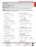
Secondly, I have no experience of Hammond transformers, unlike MelB, but they do provide a 'Design Guide' for their PT ranges used in various rectifier/capacitor/inductor situations.
You can see for capacitor input that they rate them I dc = I ac and as you would expect from that for choke input I dc = 1.54 x I ac.
Alan
First there are no heater supplies from it and at 160mA HT there is a 20% margin. And it does not run excessively hot.
More margin would always be better, I agree, but isn't this how we learn for the next project? In transformer world ''Bigger is always better''!
Secondly, I have no experience of Hammond transformers, unlike MelB, but they do provide a 'Design Guide' for their PT ranges used in various rectifier/capacitor/inductor situations.
You can see for capacitor input that they rate them I dc = I ac and as you would expect from that for choke input I dc = 1.54 x I ac.
Alan
Attachments
Last edited:
- Status
- This old topic is closed. If you want to reopen this topic, contact a moderator using the "Report Post" button.
- Home
- Amplifiers
- Tubes / Valves
- Reducing gain in a monoblock