Hi,
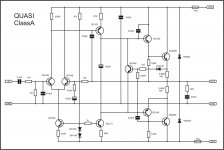
I need some help regarding Quasi's Nmos200. I have build one using the schematic provided on his website. used 50 + 50 volts as power supply and used just one pair of irf840 as i only need 100watt power. also for VAS i have used BD139/BD140 (T6 / T7). but VAS transistors and BC546(T8) and R12/R12 (47ohm) blowup fast as i try to input some signal. working fine when there is no signal or very low signal on input. also i have adjust quiescent currrent to 30mA and dc offset to less then 10ma using this method.
can some one please guide me where i am doing wrong and what i should do to get this resolved.
Thanks
I need some help regarding Quasi's Nmos200. I have build one using the schematic provided on his website. used 50 + 50 volts as power supply and used just one pair of irf840 as i only need 100watt power. also for VAS i have used BD139/BD140 (T6 / T7). but VAS transistors and BC546(T8) and R12/R12 (47ohm) blowup fast as i try to input some signal. working fine when there is no signal or very low signal on input. also i have adjust quiescent currrent to 30mA and dc offset to less then 10ma using this method.
1. Check the power supply is operating correctly and verify the rail voltages. Switch the power
supply off and check with a multimeter that the rail capacitors have discharged.
2. Correctly connect the ground, positive and negative leads to the power amp module.
3. Remove the PCB fuses and replace with 100 ohm 5 watt resistors. Connect a multimeter
that is set to the 20 volt scale across the positive rail 100 ohm resistor.
4. Check that the power supply connections are correct one last time and switch on. If the
multimeter reading goes off-scale, turn off immediately and find the problem. Check also the
100 ohm 5 watt resistors; they may have gone open cct.
5. If everything seems ok adjust VR2 to set the output stage bias current, by measuring the
voltage across the positive rail resistor. Adjust for a reading of 3 volts per output FET pair. I.e.
For a 6 FET board set for a voltage of 9 volts. This equates to a bias current of 30mA per
FET pair or 90 mA total. For a 10 FET board set for a voltage of 15 volts.
6. If everything seems ok, check the output offset voltage and adjust VR1 to achieve an offset of
less than 10 mV.
7. All being well switch off, back off the bias control trimmer (VR2) and replace the 100 ohm
resistors with 10 ohm 1 watt resistors. Switch on again and re-adjust VR2 to get 0.3 volts per
per FET pair across the positive rail 10 ohm resistor.
8. Switch off, remove the resistors and put the fuses back in. Switch on, re-check the offset
voltage and adjust with VR1 if necessary.
can some one please guide me where i am doing wrong and what i should do to get this resolved.
Thanks
Last edited:
1pair of irf840 is not sufficient for a reliable 100W of maximum output power.Hi,
I need some help regarding Quasi's Nmos200. I have build one using the schematic provided on his website. used 50 + 50 volts as power supply and used just one pair of irf840 as i only need 100watt power. also for VAS i have used BD139/BD140 (T6 / T7). but VAS transistors and BC546(T8) and R12/R12 (47ohm) blowup fast as i try to input some signal. working fine when there is no signal or very low signal on input. also i have adjust quiescent currrent to 30mA and dc offset to less then 10ma using this method.
can some one please guide me where i am doing wrong and what i should do to get this resolved.
Thanks
You need ~ 400W of total Pmax for each channel to get a reliable 100W power into severe reactance speaker with decent heatsinking and domestic type duty.
Pmax irf840 = 125W therefore 1pair comes to 250W and that is good for ~ 65W
2pair would do ~130W, but the maximum Ic is still only 16Apk
Note that these very high voltage devices have Ic = 8A and the SOA plot does not show DC nor 100ms curves. this probably indicates these are purely switching devices. You may find that the DC SOA is far below 125W at 100Vds
1pair of irf840 is not sufficient for a reliable 100W of maximum output power.
You need ~ 400W of total Pmax for each channel to get a reliable 100W power into severe reactance speaker with decent heatsinking and domestic type duty.
Pmax irf840 = 125W therefore 1pair comes to 250W and that is good for ~ 65W
2pair would do ~130W, but the maximum Ic is still only 16Apk
Note that these very high voltage devices have Ic = 8A and the SOA plot does not show DC nor 100ms curves. this probably indicates these are purely switching devices. You may find that the DC SOA is far below 125W at 100Vds
Thank you AndrwT for guiding me.
So 2 pairs of IRF840 is fine or what you suggest? i am using 50+50 supply. the burn up issue of VAS stage resolved by replacing BD139/140 with MJE340/350. i have used 2 pairs of irf840 but the bass on subwoofer (3 ohm 130watt) is not that solid as i expected. on high bass signal cone of speaker seems as it will come out of the frame. this is my first try to build an amplifier and i am not that happy with it. i am building 2.1 channel system. can you please guide me further.
Last edited:
+-50Vdc supply from a 35-0-35Vac transformer will give a maximum output of ~40VpkHello Apex sir
Sorry for very let asking.
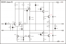
I have 35-0-35VAC 350VA transformer And one pair of 2sc5200 can I use b550 circuit and PCB, what other changes I have made in circuit & how many watts I can get on 8 Ohm load.please help
P=IV=I^2R=V^2/R
For peak of sinewave the formulae become
P=Ipk*Vpk/2=Ipk^2*r/2=Vpk^2/R/2
You have the voltage and load information so you use the version P=Vpk^2/R/2
guess what, it comes out as 100W into 8r0
The maximum reliable output from a pair of 1943/5200 is Pmax/6 = 2*150/6 = 50W
That is half what the 35-0-35Vac transformer is capable of forcing through the output stage. Don't use one pair of 1943/5200.
...The maximum reliable output from a pair of 1943/5200 is Pmax/6 = 2*150/6 = 50W...
I am not sure i understand the logic in that Pmax/6 formula, but i disagree, because that ignores both the load and the power supply, and they are the ones that dictates how much power can be safely drawn from any one pair. And more so, it would mean that one single pair of 5200/1943 cannot even give 100W onto 4 Ohms, and there are loads of amplifier that does provide exactly that, 100W onto 4 Ohms...
Hello Apex sir
b550 amp circuit with op 2sc5200, +-35v is enuff for one pair of 5200.Help if any other changes required in circuit.And which PCB layout is correct, please mention,
For +/-35Vcc power supply one single pair is enough, but you said you have a 2x35Vac transformer, if that is what you will use, then one single pair is risky even with 8 Ohm loads.
Last edited:
do a temperature de-rated SOAR for the 1943/5200 with a 45degree phase load (moderate reactance speaker) and with a 60degree phase load (severe reactance speaker) and see what you get for peak transient stresses.
If you don't know how to do that, then download David Eather's article.
Or just go and read R.Cordell. He explains it differently, but comes out with virtually the same answers
If you don't know how to do that, then download David Eather's article.
Or just go and read R.Cordell. He explains it differently, but comes out with virtually the same answers
For +/-35Vcc power supply, one single pair is enough, but you said you have a 2x35Vac transformer if that is what you will use, then one single pair is risky even with 8 Ohm loads.[/QUOTE]
thanks MarianB
NO, I start with the single pair on +-35V(8Ohm load) then upgrade to more, is it safe use 2*35VAC with 2 pairs of 2SC5200.And which semantics, PCB layout is correct.
thanks MarianB
NO, I start with the single pair on +-35V(8Ohm load) then upgrade to more, is it safe use 2*35VAC with 2 pairs of 2SC5200.And which semantics, PCB layout is correct.
Last edited:
- Home
- Amplifiers
- Solid State
- QUASI Amplifier for Beginners