Lumba Ogir said:Tibi,
it is very hard to achieve dynamically accurate error correction. The problems are many, basically Time.
Why are you saying that?
Yes, you are right, but TIME is a problem for all amplifiers.
Time means to get all spectral components in TIME.
I had a look on history messages and found your comments vis a vis some Borbely designs.
Regards,
Tibi
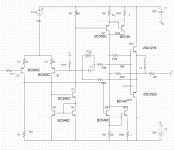
This is the test circuit schematics the class A has open loop gain of 24dB when terminated with 100 Ohms its Z0 has been measured - roughly 80 Ohms. The new elements are R23 R25 R26
R25 must eventually be a capacitor in parallel with R. L will be quite high about 50 uH. R23 compensates the series real resistance of inductor L.
R25 must eventually be a capacitor in parallel with R. L will be quite high about 50 uH. R23 compensates the series real resistance of inductor L.
Attachments
pintur said:
...but not too fast in order to allow the class A stage (with its connected capacitances) to react in time!
Regards,
Pintur
Pintur,
Really I don't understand your statement.
Why a fast device can not be used after a slower class A stage ?
On other hand why the class A stage to be slower? Input capacitance on MOSFET at Vds >= 50V is very low.
Regards,
Tibi
No it is around 1.5 nf for vertical and even more for horizontal. AND it depends in non linear fashion on Vgs. This complicates analysis in time domain considerably. In switching applications FETs are driven by push pull BJTs as the transition current exceeds 1 amp by far.
Tibi,
Particularly when negative feedback used for correction. Our senses cannot stand time errors.Yes, you are right, but TIME is a problem for all amplifiers.
Harmonic distortion never brings about deviations in time.Time means to get all spectral components in TIME.
FETs are nice but not best in every location.I had a look on history messages and found your comments vis a vis some Borbely designs.
hahfran said:No it is around 1.5 nf for vertical and even more for horizontal. AND it depends in non linear fashion on Vgs. This complicates analysis in time domain considerably. In switching applications FETs are driven by push pull BJTs as the transition current exceeds 1 amp by far.
You mean vertical and lateral MOSFET.
")
Verticals exihibit higher capacitance than laterals, but if you look at datasheet this is given at Vds=10V. As Vds is increasing, input capacitance will decrease significantly. Laterals have lowest input capacity. For example BUZ901 have Ciss as lower to 500pF at Vds=10V. This MOSFET can easily reach 300Mhz and his linearity is very very good even at low Ids.
As you may know, lateral MOSFET's are the most rugged devices.
In my opinion these MOSFETS are the king of output power devices.
Don't mix vertical MOSFET with very low ON Rds - used in switching applications - , with lateral MOSFET which are extremly linear devices.
Regards,
Tibi
I am not quite sure its a long time ago I studied engineering sciences but I do not think negative feedback can introduce time errors. Time errors are introduced by loudspeakers. Time error requires something like a memory or a sample and hold.
You have a time error when a mechanical system such as a loudspeaker does nothing for say 20 msec after its voice coil
receives an electric signal. But it "stores" the received electrical energy and responds with a motion of the diaphragm after 20 msec. Basically every semiconductor device must produce time errors but the physical theory is different for BJTs and FETs.
All this stuff re negative feedback is treated with Bode and Nyquist stuff in frequency domain not in time domain.
I mentioned already that just because of Bode Nyquist criteria
one has to determine the capacitor in the current dumping amp first it is not an independent choice rather it depends first on the power transistors.
Lumba Ogir said:Tibi,
Particularly when negative feedback used for correction. Our senses cannot stand time errors.
Harmonic distortion never brings about deviations in time.
FETs are nice but not best in every location.
Well, I don't agree with you.
Our senses can easily hear time errors.
Many people are running for very low THD when in fact they are facing timing problems.
And NF is a must in a good design.
Regards,
Tibi
Please read what I`m trying to say.
http://www.diyaudio.com/forums/showthread.php?s=&threadid=118826&perpage=25&pagenumber=1
http://www.diyaudio.com/forums/showthread.php?s=&threadid=118826&perpage=25&pagenumber=1
I studied auditive perception quite a bit. To recognize a pitch takes human brain 50 msec. No we do not hear time errors with this sense.
But there is a second much faster auditive perception that is to locate a sound source and its size. This sense detects time errors quite well but as a misread or misinterpretation of location and size. Narratively this sense pretty soon gets bored with reproduced sound fields. Then the thrill is gone no matter how low THD is or how flat frequency response is. An acoustical musical instrument is identified by its spectrum of harmonics and by the rise time of the particular harmonics. The latter is interpreted as size. A woofer supported by a resonance system such as a vented box or a pipe reproduces an acoustical bass as arbitrarily large. This is not due to harmonic distortion but to time error the first harmonic rises much slower than that produced by the original.
Btw my cats tests loudspeakers for timing errors. If they do not react to the reproduced rattling of a mouse or tripping of a bird
on dry leaves the speaker has for sure time errors.
tvicol said:
Pintur,
Really I don't understand your statement.
Why a fast device can not be used after a slower class A stage ?
On other hand why the class A stage to be slower? Input capacitance on MOSFET at Vds >= 50V is very low.
Regards,
Tibi
Hi Tibi,
here what Bernd Fritz Ludwig states in his paper "QUAD-405 Modification (and related stuff), version 1/2004":
- about drivers substitution:
"The 'upper driver' (TR7) is part of the 'class-A-stage', and it might thus be tempting to try an upgrade from the venerable RCA 40872 (~BD244D, 5MHz) to a faster device (f. e. Motorola's 30Mhz-MJE15031, MJE15033, or Toshiba's 2SA1930). But there is absolutely no use in this kind of 'update': At very low levels (and that is: everywhere outside the audio-range) the 'pre-drivers' (Tr3/4) alone determine the maximumspeed of the stage (via C11) -- and they are much faster than the driver itself. -- Further it would be a VERY bad idea to upgrade the 'lower driver' (Tr8) by a faster device since it is part of the dumpers, where high speed is rather unwanted (speed is even reduced intentionally by R37/L1/[C19] or R37/L4 [later]). So everything seems to be perfect with the 'cheap' and 'slow' drivers."
-about dumpers substitution:
"A state-of-the-art choice for upgrading might be Toshiba's recent 2SC5200 (or 2SC5359) which replaced the recommended SC3281 in ~1997 (be careful: by now most devices ed “Toshiba2SC3281” are just fakes - something like 2N3055s in TO-264-cases!). Motorola's improved copy, MJL3281A, seems to be still in production, and recently ON-Semiconductors introduced the MJL4281A.
They all have nearly constant dc-current-gain of about 100 from 10mA up to ~7A (with the older types gain drops from about 50 at 3A to less than 30). But unfortunately they are very fast (CGBP ~30Mhz) and thus not wholly uncritical. There is no benefit from increased dumper-speed here, on the contrary: if the dumpers open too fast, the class-A stage may be too slow (due to C8) to react in time.
Test for overshot with 1kHz square-wave. Usually ~1nF (ceramic) from collector to base of Tr10 (like C19 in some issues of the 405-1) will help already. (If you are lucky, C19 and R41/L3 are present on your board [sn. 9000 to 59000]; this will put you onto the safe-side anyway).
Motorola's MJL21194 and 21196 (a kind of improved 15024) are more conservative alternatives: they are not that fast (CGBP ~7MHz) and they show nice current-gain characteristics up to 5A as well (which is, obviously, more than ample, at least with double-output-devices). 'MJ' indicates TO-3 at Motorola, 'MJL' is TO-3P(L)/TO-264, so look for the 'L' here, since all are available in 'classical' TO-3 as well.
Maybe even some TO264-versions of MJ15003 are (or will be) available."
Otherwise what is the task of L1 and, in some versions, of L3 in the Quad original circuit? To increase the open time of the dumpers, I think.
Regards,
Pintur
Hi Pintur,
I don't agree with all Bernd Fritz Ludwig statements.
- about drivers substitution:
I found a big sound improvement by changing BD244D with MJE15033 and later with FJP1943. These two devices are more linear and exhibit less miller effect. If I need a slow device I always prefer a fast one and compensate with a real capacitor.
And in QUASAR is no C11.
-about dumpers substitution:
First QUASAR is a different design, but
"There is no benefit from increased dumper-speed here, on the contrary: if the dumpers open too fast, the class-A stage may be too slow (due to C8) to react in time"
This statement have no sense.
On the contrary. I fond that fast devices will make error correction bridge working in time - no more spikes. In fact in all these theoretical current dumping analysis, we work with theoretical components, which are faster than real ones. Get fast man !
Regards,
Tibi
hahfran,
More explicitly, separate sensory systems for time and frequency, everything beautifully compiled by the brain.
The latter easily detects any crossover distortion, time deviations caused by GNF and by other deficiencies.
It gets tortured and exhausted by muddled sound fields resulting in extremely short listening sessions. Unfortunately, we do not have a separate sense, immune to time errors, for artificially reproduced sounds.
More explicitly, separate sensory systems for time and frequency, everything beautifully compiled by the brain.
I studied auditive perception quite a bit. To recognize a pitch takes human brain 50 msec. No we do not hear time errors with this sense. But there is a second much faster auditive perception that is to locate a sound source and its size.
The latter easily detects any crossover distortion, time deviations caused by GNF and by other deficiencies.
Narratively this sense pretty soon gets bored with reproduced sound fields.
It gets tortured and exhausted by muddled sound fields resulting in extremely short listening sessions. Unfortunately, we do not have a separate sense, immune to time errors, for artificially reproduced sounds.
The question is can one map a subjective impression onto allegedly objective results? That is, scientifically, a bijective map.
That would mean, the subjective impression can be exactly forecasted by "objective" measures.
Basically, this is known as "Einstein's Moon". Einstein claimed the moon is there -exists- whether or not there is someone to observe the moon. Is this objective moon the moon? No it isn't.
It is a description of attributes, the description - or map, or theory- is consistent but necessarily incomplete. Now do we enjoy music or do we enjoy the consistent description of its attributes ( that is what is recorded on a CD )?
Art is complete but inconsistent. It is impossible to repeat exactly
Jarrett's Coeln concert because there was not any stringent reason to play exactly as he did.
So it is not repeatable as there is no start point.
This is a narrative excerpt from cognitive science nevertheless one can conclude therefrom what an amplifier and a loudspeaker is permitted to add as errors, and what is forbidden.
Harmonics are permitted provided these are the harmonics the musical instrument produces itself. A trumpet does not produce the harmonic spectrum of crossover distortion. Except the musician wants it to produce something like crossover distortion.
Time errors are forbidden.
hahfran,
we have limited means at our disposal with respect to available technical knowledge and reliable methods of analysis hindering exact estimations. On the other hand, in my opinion, the results do not need to be verified objectively. Personally, I´m not interested in any kind of measurement data concerning sound quality.
we have limited means at our disposal with respect to available technical knowledge and reliable methods of analysis hindering exact estimations. On the other hand, in my opinion, the results do not need to be verified objectively. Personally, I´m not interested in any kind of measurement data concerning sound quality.
Tibi,
I agree, the discussion is unilaterally focused on the error correction putting aside basic sonic and topological considerations. The idea of using devices with inferior properties would be advantageous is absurd.
hafran,
life is not easy (and not fair). What are you gonna make up to get things right (in time)?
The first tests with class A amp and FET power stage do in fact confirm theory! It is well possible to null out crossover distortion errors but exactly as theory predicts only for a small frequency range. In practice if I opt for the hard side and trim crossover distortion at full load at 10 kHz I see big crossover distortion at 1 kHz - it cannot be otherwise. However a practically feasible approach is to trim error compensation at 1 kHz or in the important frequency of 500 Hz. I am testing with a pair of quite old 2SK135 2SJ50 these were once selected as matching pair as far as that is possible with FETs ( in theory it is not possible due to the different carrier mobilities ). When I changed this matched pair for another also matched pair of 2SK135 2SJ50 I had to rerun the error trimming procedure at full. Not just really convincing and not promising, either.
It is just so as theory predicts one has to go for 100dB open loop gain and >100 MHz gain bandwidth product to really become independent of characteristics of the power stage devices.
I will now do some test with BJTs.
Btw if life were fair Elvis were still with us and his imitators had never existed.
hahfran,
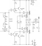
2SK135/2SJ50 are sonically superior to anything else, please without hesitation look at this previously suggested suitable design equipped with genuine single-ended input and evenly genuine CFP output stage.
(Another option is disposing of them for many bucks).
http://www.diyaudio.com/forums/atta...tamp=1225821617
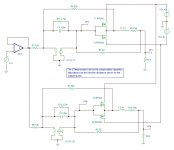
A simple SPICE simulation (such as the attached TINA schematic) will show that the performance using a voltage-amplifer or a transconductance amplifier for the Class-A stage makes very little difference to the measured performance.
I have used a VCVS and a VCCS for the class-A stages so that it's very easy to alter the voltage or current gain of the stage to perform the simulation runs.
I use two QUAD 405s with the original amplifier boards replaced my my own current-dumping design, and still think the this principle is still up there with the best when it comes to amplifier topologies. Peter Walker was a very bright guy to come up with the idea. It's just a pity that the original implementation was so poor.
Attachments
- Home
- Amplifiers
- Solid State
- QUASAR a reborn design