Here the link to a very exhaustive document of Bernd Ludwig about current dumping theory, where the author explains the role of C8 and the reason why fast dumpers are not advisable in this topology:
http://www.dc-daylight.ltd.uk/Valve-Audio-Interest/QUAD/QUAD-405-Modification/405_Qw_7.pdf
Regards,
Pintur
http://www.dc-daylight.ltd.uk/Valve-Audio-Interest/QUAD/QUAD-405-Modification/405_Qw_7.pdf
Regards,
Pintur
tvicol said:
I think is good to read and digest John Vanderkooy and Stanley P. Lipshitz document.
http://quad405.com/jaes.pdf
Tibi
Ok this paper after all contains what is missing in Albinsons/Walker paper. Now we have the necessary design considerations.
tvicol said:
...
Bridge resistors will determine class A gain as well.
...
Clarification: only R11 and R12 are part of negative loop. R10 is part of negative loop but out of current dumping bridge.
Tibi
Hevreng's consistent analysis gives the DIY an excellent tool to design forward correction amps on a safe basis. One could start up from a well designed class A driver with known properties.
It shows also that FETs as dumpers provide no advantage.
Rather BJTs with a linear Ib/Ic characteristic fit the analysis quite well. After all the idea makes now sense to me.
It shows also that FETs as dumpers provide no advantage.
Rather BJTs with a linear Ib/Ic characteristic fit the analysis quite well. After all the idea makes now sense to me.
Ps. I also prepare a SMPS for DIY community. Hope this will generate more interest.
JaJaJA!!
An quiet audio-SMPS is definitely missing here!!
Have fun, Hannes
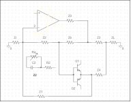
The Quad 405 error null balance condition does not hold in a real world as the class A amplifier gain is not infinite and it does not have an infinite gain bandwidth product either. That means its output impedance Z0 is not zero.
In the real world the error null condition reads
Z2*Z4=Z1*Z3+ ( Z1*Zb +(Z1*Z3*Zb/Z0))
If gain is infinite Z0 is zero and Zb is zero so in this case the last term in brackets is 0/0 and here that yields 0 so we have the familiar but unrealistic Quad current dumper condition Z2*Z4=Z1*Z3
A usual common emitter voltage amplifier in class A may have Z0 in the range of 50-100 Ohms this cannot be neglected.
It is no longer feasible without further consideration to have Z2 as a capacitor and Z4 an inductor. Favorably Z2 should be a capaictor in series with a resistor to determine unity gain frequency.
So in practice one must have an integrated IC opamp as class A amplifier having a very high open loop gain and also high open loop bandwidth. It is feasible to realize a current dumping error corrected power amp with a low open loop gain discrete class A amp but thir requires a lot of engineering elaborate.
Attachments
hahfran,
That price is too high according to my consideration.So in practice one must have an integrated IC opamp as class A amplifier having a very high open loop gain
How much work would it take for you?It is feasible to realize a current dumping error corrected power amp with a low open loop gain discrete class A amp but thir requires a lot of engineering elaborate.
A big lot of work and equipment that would be outright too expensive. The not-nulled error shows up as small spikes in the
zero cross region of the signal and that is nothing but crossover distortion. One had to start up by calculating C2 and R2 to determine the unity gain frequency of the class A and has to have
Zi,Z1, Z3 variable. Further the inductor Z4 has an inevitable series resistance which must also be compensated with Ra.
It is all feasible but the result won't be significantly better than
a standard negative feedback however with lots more tuning effort. At the very end of the analysis it turns out why forward error correction never made it into mass production amps , with the exception of Quad.
As originally patended by Black, error correction requires 2 amps having very precisely controlled gain ( frequency dependend ) and how does one achieve precise gain control? Well yes by applying negative feedback....
I have a discrete class A amp board with well known properties
in terms of gain, output impedance, and will try a test current dumping amp with FETs as dumpers and will see whether the very unfavorable spikes are more easy to trim away. However I think it will be worse with FETs.
Forward error correction is a wide field for DIY. In the schematic
Zb could be implemented as a signal controlled variable resistor i.e. by a FET.
The class A could be a hybrid , tubes for voltage gain and a push pull FET output delivers current i.e transforms voltage to current.
Zb could be implemented as a signal controlled variable resistor i.e. by a FET.
The class A could be a hybrid , tubes for voltage gain and a push pull FET output delivers current i.e transforms voltage to current.
I will give it a try as far as I can do being equipped with an antique Tektronix 2 channel scope and an also antique Wein bridge sine generator, and a dual power supply. If, as I suspect, every amp has to be fine tuned individually it is not the right solution for my project to make at least 6 identical amps for active speakers. The problem of oscillation that has shown up with the Quad 303 triple cascade when using fast BJTs as power devices should be solvable generally. And it sounds quite good even with slow epibase BJTs yet does not meet the > 50 volts/usec rise time spec.
Yes I am confident the problem could be solved with careful selection of BJTs, or an RC to determine unity gain frequency, and matching of the phase characteristics of driver and power stage.
However as the pre-driver has no differential amp in input and no current sources - killers of sound, imo - it has poor CMRR and must have a separate power supply and a DC offset correction with an opamp.
However as the pre-driver has no differential amp in input and no current sources - killers of sound, imo - it has poor CMRR and must have a separate power supply and a DC offset correction with an opamp.
hahfran,
in my usually peculiar view:
in my usually peculiar view:
The best way go.Yes I am confident the problem could be solved with careful selection of BJTs
Deteriorating.or an RC to determine unity gain frequency
Has many advantages.must have a separate power supply
What`s even worse, it produces unfavorable harmonic spectrum.However as the pre-driver has no differential amp...has poor CMRR
hahfran said:The Quad 405 error null balance condition does not hold in a real world as the class A amplifier gain is not infinite and it does not have an infinite gain bandwidth product either. That means its output impedance Z0 is not zero.
In the real world the error null condition reads
Z2*Z4=Z1*Z3+ ( Z1*Zb +(Z1*Z3*Zb/Z0))
If gain is infinite Z0 is zero and Zb is zero so in this case the last term in brackets is 0/0 and here that yields 0 so we have the familiar but unrealistic Quad current dumper condition Z2*Z4=Z1*Z3
That's why in first QUAD's class A stage is a triplett follower, ensuring a huge gain. Later this was changed to a dublet, which still offer lot of gain and above condion is satisfied quite well.
hahfran said:A usual common emitter voltage amplifier in class A may have Z0 in the range of 50-100 Ohms this cannot be neglected.
It is no longer feasible without further consideration to have Z2 as a capacitor and Z4 an inductor. Favorably Z2 should be a capaictor in series with a resistor to determine unity gain frequency.
So in practice one must have an integrated IC opamp as class A amplifier having a very high open loop gain and also high open loop bandwidth. It is feasible to realize a current dumping error corrected power amp with a low open loop gain discrete class A amp but thir requires a lot of engineering elaborate.
Well this is not quite a must. A good example is QUAD where opamp is not part of class A stage.
Regards,
Tibi
hahfran said:...
I have a discrete class A amp board with well known properties
in terms of gain, output impedance, and will try a test current dumping amp with FETs as dumpers and will see whether the very unfavorable spikes are more easy to trim away. However I think it will be worse with FETs.
Give it a try.
")
I didn't see any "unfavorable spikes" in all my QUASAR amplifiers. And I made several till now.
Dupers need to be faster enough to follow class A stage.
Peter Walker wrote in Wireless World December 1975:
"We have said that the dumpers have to be sufficiently fast to come to the rescue of the class A amplifier to prevent its overloading. Clearly they must be sufficiently fast to achieve this over the audio spectrum of the programme."
Regards,
Tibi
Lumba Ogir said:hahfran,
I comprehend, it`s not worth it. This technique demands a practically almost unattainable precise balance. I`ve always had a strong suspicion about all kinds of error correction.
What are you planning to do, if I may ask?
It is worth and I strongly believe in error corection amplifiers.
But seems that you don't like even Borbely designs ...
Regards,
Tibi
Tibi,
it is very hard to achieve dynamically accurate error correction. The problems are many, basically Time.
it is very hard to achieve dynamically accurate error correction. The problems are many, basically Time.
Why are you saying that?But seems that you don't like even Borbely designs ...
tvicol said:
Give it a try.
I didn't see any "unfavorable spikes" in all my QUASAR amplifiers. And I made several till now.
Dupers need to be faster enough to follow class A stage.
Peter Walker wrote in Wireless World December 1975:
"We have said that the dumpers have to be sufficiently fast to come to the rescue of the class A amplifier to prevent its overloading. Clearly they must be sufficiently fast to achieve this over the audio spectrum of the programme."
Regards,
Tibi
...but not too fast in order to allow the class A stage (with its connected capacitances) to react in time!
Regards,
Pintur
The error null condition holds for very high open loop gain of class A AND for very high open loop gain bandwidth product AND for dumper drive current that is proportional to signal amplitude.
This is just not the case if dumpers are FETs because then the drive current is proportional to the first derivative of signal to time multiplied with signal amplitude. At least from theory I do not see how this could be compensated, or , error nulled.
If one has to design for gain 90 dB and gain bandwidth 100 Mhz
then one could as well bring this down to 20 dB with application of negative feedback. Of course this will not reduce crossover distortion significantly. There is the distinct advantage of the current dumping. The disadvantage is that one has to match the
upper frequency limits of dumpers and class A driver and a simple way to achieve that is to have an RC feedback of the class A. Then however the Quad error null condition does not hold.
- Home
- Amplifiers
- Solid State
- QUASAR a reborn design