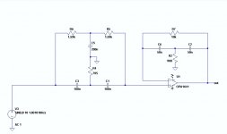
I found the Twin T Bridged T circuit I mentioned.
The Bridged T is a high Q band pass filter and is tuned above the Twin T.
There is no feedback used in the Twin T section.
The Bridged T is a high Q band pass filter and is tuned above the Twin T.
There is no feedback used in the Twin T section.
Attachments
Last edited:
I found the Twin T Bridged T circuit I mentioned.
The Bridged T is a high Q band pass filter and is tuned above the Twin T.
There is no feedback used in the Twin T section.
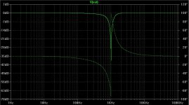
Bingo, if you build an auto track able notch, this would be the solution! While a 1.00KHz without auto track, as given in your graph would be only about -40dB.
Hp
can the qa401 be used with REW or arta ?
Probably not directly. The QA401 software is proprietary. They do supply software APIs to allow external programs to call analysis functions, but I haven't heard anything about ARTA using those.
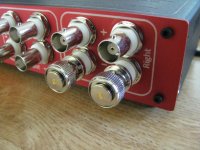
Shorting BNC caps for the QA401
Here is a recommendation for BNC shorting caps for the QA401 when being used as single-ended. Amp #202114 which is Mouser 523-202114 or Digikey ACX1069-ND:
http://www.mouser.com/ProductDetail/Amphenol/202114
I couldn't tell from the datasheet if it was 0 ohm, 50 or 75. I got a few in this week and the part really is a 0 ohm short. The pin appears to be a press-fit into the cap. No attached chain.
Attachments
Last edited:
I remember those! ") The old coax daisy chain Ethernet. That would take down every Sun/SGI workstation on the chain whenever anyone had to break the chain to move coax around or add/remove a workstation.
The old coax daisy chain Ethernet. That would take down every Sun/SGI workstation on the chain whenever anyone had to break the chain to move coax around or add/remove a workstation.
Lol and nobody really knew the lengths of any of the coax segments roaming around inside the walls, the drop ceilings, and computer floors. Everybody would just grab a BNC T and some coax and splice in their new workstation.
The old coax daisy chain Ethernet. That would take down every Sun/SGI workstation on the chain whenever anyone had to break the chain to move coax around or add/remove a workstation. Lol and nobody really knew the lengths of any of the coax segments roaming around inside the walls, the drop ceilings, and computer floors. Everybody would just grab a BNC T and some coax and splice in their new workstation.
Last edited:
QA401 generator signal width
I understand this now! firev1 was exactly correct.
I had a bit of a discussion with QA regarding measuring notch filters and this issue came up. I had to go back and review FFT bins and FFT spectral leakage since its been years since I used this stuff.
FWIW here is a good summary of bins from the net:
Introduction - FFT Size
and spectral leakage:
frequency spectrum - Why does spectral leakage arise in an FFT? - Signal Processing Stack Exchange
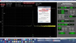
The key is the "rounding" function check box in the QA generator properties. In the first two plots below the rounding box is checked, which is the default. The resulting loopback plot has the nice narrow width. Notice that the generator is set for 1.00 KHz in the properies window, but see what the mid-bin rounded frequency turned into at the top of the screen. That add-on to the 1KHz is an integer division into the frequency resolution number at the top of the screen. That first link above shows how to calculate the frequency resolution.
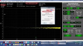
The next two are with the rounding function turned off. Now the base of the 1.00 KHz fundamental is wide, like it is with Victor's oscillator, because that frequency is no longer mid-bin. Up at the top of the screen though the frequency now reports as exactly 1.00 KHz. That was the discussion with QA - for measuring notch filters the rounding should be off to get an exact frequency and the flat top should be selected, they say. I've run a notch filter test here with the QA
http://www.diyaudio.com/forums/equi...erential-notch-q401-part-1-a.html#post4709636
that way and it came out great. If the notch filter was exactly centered at 1.00 KHz and the QA401 generator rounding was turned on, the genrator signal would miss the notch center by almost 2 Hz, with the FFT window and sample size numbers used here. But with rounding turned off it would hit the notch dead on.
1) Why is the bottom of the sine wave so narrow from the internal oscillator and wider on the external oscillator? (looking at the -100 to -130+ dB range on the 1K signal)
Late to the party but simply put, QA makes use of coherent sampling(the oscillator frequency is always set according to the fft bin length).
If you take a look at QA measurement plots, the 1khz test frequency is never matched at 1khz but offset a little so that an integer number of cycles is always captured within the FFT length set. This results in almost no widening of the skirt.
I understand this now!
firev1 was exactly correct.I had a bit of a discussion with QA regarding measuring notch filters and this issue came up. I had to go back and review FFT bins and FFT spectral leakage since its been years since I used this stuff.
FWIW here is a good summary of bins from the net:
Introduction - FFT Size
and spectral leakage:
frequency spectrum - Why does spectral leakage arise in an FFT? - Signal Processing Stack Exchange
The key is the "rounding" function check box in the QA generator properties. In the first two plots below the rounding box is checked, which is the default. The resulting loopback plot has the nice narrow width. Notice that the generator is set for 1.00 KHz in the properies window, but see what the mid-bin rounded frequency turned into at the top of the screen. That add-on to the 1KHz is an integer division into the frequency resolution number at the top of the screen. That first link above shows how to calculate the frequency resolution.
The next two are with the rounding function turned off. Now the base of the 1.00 KHz fundamental is wide, like it is with Victor's oscillator, because that frequency is no longer mid-bin. Up at the top of the screen though the frequency now reports as exactly 1.00 KHz. That was the discussion with QA - for measuring notch filters the rounding should be off to get an exact frequency and the flat top should be selected, they say. I've run a notch filter test here with the QA
http://www.diyaudio.com/forums/equi...erential-notch-q401-part-1-a.html#post4709636
that way and it came out great.
If the notch filter was exactly centered at 1.00 KHz and the QA401 generator rounding was turned on, the genrator signal would miss the notch center by almost 2 Hz, with the FFT window and sample size numbers used here. But with rounding turned off it would hit the notch dead on.Attachments
Last edited:
More beginner questions
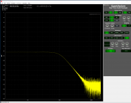
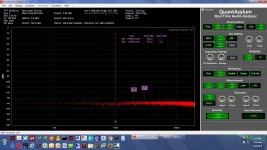
I'm having a hard time putting a cursor directly on 1kHz - it doesn't want to go where my mouse is. The reason is, I'd like to measure the slope of this crossover. I'm expecting it to be 1kHz LPF at 24dB/octave.
Is it possible to "hold" a graph, while I configure the crossover at a different slope and display the graphs on the same axis?
Also, perhaps a bug, but it sure seems like under the generator functions, the left and right channel muting options are swapped in the software (right mutes left, and vice versa)?
Any recommendations on my settings, per the screenshot below?
Attachments
Need a PLL... Phase Locked Loop?
Phase lock the notch filter to the incoming signal.
-RNM
Yeah there is a nifty article out there I found once via Google that used a universal switched capacitor filter and a PLL to form a tracking notch filter. The THD with a switched cap filter would probably be too large, but I'll bet something similar could be done with the Fliege notch filter and a PLL. Replace one of the two resistors in the frequency set votlage divider with a phototransistor.
More beginner questions
Hey I have some information for you but your PM inbox is full, at least as of a few days ago.
I don't know the answers to the other questions but I did just try those generator mute fuctions. On mine they are working correctly, left mute does mute the left and vise versa for right. I tried it on both generators. There is a new V1.47 QA401 software release out as of a week or two ago that fixes a bunch of stuff. The first thing on the list of fixes is "Flipped TX audio Left and Right" - maybe that is it. In my case the "link" and "run" LEDs were not coming on and were one of the fixes.
http://www.quantasylum.com/content/Support/Downloads.aspx#QA401
Looks like one of the fixes is a notification when a new version is out!
Last edited:
Yeah there is a nifty article out there I found once via Google that used a universal switched capacitor filter and a PLL to form a tracking notch filter. The THD with a switched cap filter would probably be too large, but I'll bet something similar could be done with the Fliege notch filter and a PLL. Replace one of the two resistors in the frequency set votlage divider with a phototransistor.
Try this http://linearaudio.nl/sites/linearaudio.net/files/25404-Notch_filter_autotunes_for_audio_applications_pdf.pdf
[I have ordered a QA401... its on its way
Hey that is fantastic news!! I'll be interested to hear your thoughts on it!
QA401 left vs. right channel different in loopback
I just discovered that the left and right channels of my QA401 are quite different in loopback. I would be curious what other folks with QA401's find here. I'm wondering if it is a design issue or a bad chip.
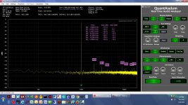
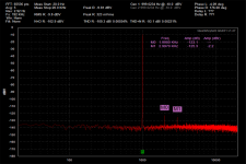
Both of these are done with a 192KHz sample rate and a 65536 point window. Hamming window, 1KHz generator with rounding, and -10dBV signal level. The left "+" generator output is looped to the left "+" input with the right "-" input shorted. Same for the right, the right "+" generator output is looped to the right "+" input with the right "-" input shorted.
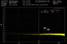
The first plot below in yellow is the left channel. It shows the 2nd harmonic at about -117.0dBV, a third at -125.6, and then a 4th and some higher harmonics.
The other plot in red is the right channel. Here it shows the 2nd harmonics at -125.0dBV and the 3rd at -122.0, then no higher harmonics.
Argh! That is -117.0dBV on the left vs. -125.0dBV on the right for the 2nd harmonic. Then a spray of high order hamonics on the left with none on the right channel. Just off the cuff I would expect a better match than that. Is anyone else getting this?
The good news here is if this turns out to be a (fixable) bad chip in the unit I'm going to be a lot happier with it. That 2nd harmonic on the left channel is a bit much, but I could live with the level the right channel is showing.
I just discovered that the left and right channels of my QA401 are quite different in loopback. I would be curious what other folks with QA401's find here. I'm wondering if it is a design issue or a bad chip.
Both of these are done with a 192KHz sample rate and a 65536 point window. Hamming window, 1KHz generator with rounding, and -10dBV signal level. The left "+" generator output is looped to the left "+" input with the right "-" input shorted. Same for the right, the right "+" generator output is looped to the right "+" input with the right "-" input shorted.
The first plot below in yellow is the left channel. It shows the 2nd harmonic at about -117.0dBV, a third at -125.6, and then a 4th and some higher harmonics.
The other plot in red is the right channel. Here it shows the 2nd harmonics at -125.0dBV and the 3rd at -122.0, then no higher harmonics.
Argh! That is -117.0dBV on the left vs. -125.0dBV on the right for the 2nd harmonic. Then a spray of high order hamonics on the left with none on the right channel. Just off the cuff I would expect a better match than that. Is anyone else getting this?
The good news here is if this turns out to be a (fixable) bad chip in the unit I'm going to be a lot happier with it.
That 2nd harmonic on the left channel is a bit much, but I could live with the level the right channel is showing.Attachments
Last edited:
1audio - hey thanks for doing the test with your unit.
I tried swapping generator outputs, right "+" into the left "-" input with the left "+" input shorted, which produced exactly the same results on the left. Looks like a receiving/ADC problem.
I tried the generator swap on the other channel and same results there too. The right channel still looks relatively clean with the left generator as the input.
I believe that I probably killed it though! I was thinking this afternoon if there was some way to determine if I caused the problem or if it was DOA. Then I remembered the unboxing photos I took in post #1907 above, then again in post #1927 with averaging turned on. The left channel looks just fine in both. Lol, I've tested it to death. I'll get in touch with QA and see about getting it repaired.
I tried swapping generator outputs, right "+" into the left "-" input with the left "+" input shorted, which produced exactly the same results on the left. Looks like a receiving/ADC problem.
I tried the generator swap on the other channel and same results there too. The right channel still looks relatively clean with the left generator as the input.
I believe that I probably killed it though! I was thinking this afternoon if there was some way to determine if I caused the problem or if it was DOA. Then I remembered the unboxing photos I took in post #1907 above, then again in post #1927 with averaging turned on. The left channel looks just fine in both. Lol, I've tested it to death.
I'll get in touch with QA and see about getting it repaired.
Last edited:
I just discovered that the left and right channels of my QA401 are quite different in loopback...
It seems my QA401 has the exact same behavior, using the same setting as yours, the left channel loopback gives 2H/3H of -118.6/-126.3dBV, whereas the right channel loopback gives 2H/3H of -123.1/-125.3dBV.
BTW, I didn't stress my QA401 at all.
Attachments
Last edited:
speaking of notch filters, I started wondering what scheme it is used in my Sound Technology 1700B sound analyzer.
I know it has a notch filter with fine tuning and also has an indicator to flag if the filter is tuned or not.
I wonder if that could be used along with a soundcard or Q401.
Anybody ever looked at the SoundTechnology's schematic? I think I had a service manual at one point
I know it has a notch filter with fine tuning and also has an indicator to flag if the filter is tuned or not.
I wonder if that could be used along with a soundcard or Q401.
Anybody ever looked at the SoundTechnology's schematic? I think I had a service manual at one point
- Home
- Design & Build
- Equipment & Tools
- QuantAsylum QA400 and QA401