I'm using 600 mV and have not seen a dramatic change with lower levels. 500 mV to 600 mV is 1.5 dB. Please try a higher resolution on your measurements. 8192 is really low resolution, useful only for very fast acquisition of a measurement.
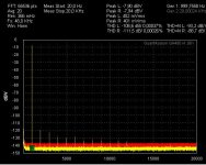
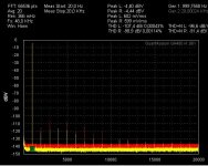
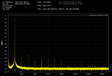
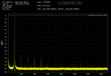
OK, attached a sequence of measurements at 400mVrms, 500mVrms, 600mVrms, 700mVrms with higher res.
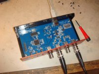
Always left chanel direct wired for reference and right chanel with buffers+filter.
Levels above 500mVrms/700mVp definitely show a dramatic impact on my QA400.
Are you sure about your 600mVrms? Your postings show 700...800mVrms.
Noise: Yes, even without averaging and without using the SNR function I mentioned this in my first post. As you say not unusual- agreed- IMHO no wonder after 5th order filtering and gain + attentuations in the range of 32db up and down... and all this with inverting gain stages and without extremly low impedances.
With increased efforts there would be options, but I intend to use the QA400 mostly for distortion measurement. So my focus is clearly to have adjustable and protective buffers and filters which don't add much distortion.
For accurate noise measurements on line level I am using a LT1028 based noise amp which has its limitation around 1.5nV/Hz say 200nVrms over audio BW.
And for accurate noise measurements behind comparators/swichtching stages or classD amps I am using a heavily filtered noise amp with approx. 30nV/Hz say 4-5uVrms over audio BW (factor 10...100 better than normal classD output numbers).
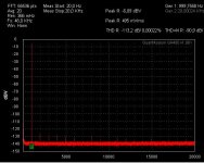
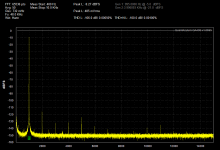
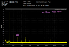
Increase of distortion above 500mVrms seems to be caused by the input. The second last picture shows the situation when going for 700mVrms at the output, but attenuating the right chanel to 500mV at the input using the buffers and filter.Choco (and Demian), it's not clear to me whether the 500mV sweet spot is just the analyzer part or also related to the QA400 source?
IOW, in loopback, what causes the rising distortion with level, the source or the analyzer?
jan
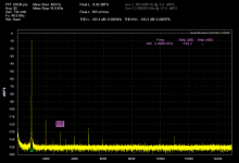
Last picture shows only the right chanel with 700mVrms output and 500mVrms input using the buffers and filter.
Another interesting point visible from the first 4 pictures is that the distortion of my input buffer and filter seems to increase above 500mVrms even more than the QA400 (comparison left vs right). Most likely related to my clamping which protects the QA400 vs voltages above +/-1.3Vp.
Attachments


Here is what I get at 500, 600, 700,1000 mV. I need to recalibrate mine, probably new software or ??? These were measured RMS levels using a seperate meter. My QA400 reports clipping at any input above 1V RMS sine wave even though it actually has good readings. The 3rd harmonic rises pretty quickly above 500 mV and the 2nd above 700 mV. The last two show the effect of source resistance (actually ithe input non-linearity of the QA400) The first is a 50 Ohm source, the second is a 600 Ohm source. The third harmonic increased by 3 dB. This is also visible on the source side using an analyzer connected in parallel.
Attachments
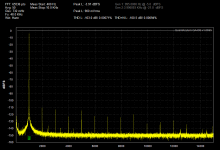
I don't think that it is an mayor issue with calibration. I calibrated mine in the beginning and it shows a good fit between scope, DMM and QA400 readings. But also without calibration there was not a big difference.Here is what I get at 500, 600, 700,1000 mV.
...hm, the differences between our both units are likely to be the random results below -100db THD+N which are specified by Cirrus for the CS4272.
http://www.cirrus.com/en/pubs/proDatasheet/CS4272_F1.pdf
Even if my unit is looking pretty nice at 500mV - there is no evidence that the displayed numbers would be correct.
Another topic could be the coupling caps inside the QA400.
If the description is right - they use an electrolytic in reversed polarity at multiple places in the signal path. Strange.
Did anyone open the QA400 and look if these e-caps are really operated with reversed polarity, or is this just an error in the description? Why would one place an e-cap in that way that it is sytematically operating in reverse polarity when a DC-free source/load is connected?
PS 1500VRMS at 20kHz in 1000pF needs 150mA if my calculation is correct:
C*dV=dI*dT where for the sake of simplicity we can assume 1500V at 20kHz being 150V/uS.
Jan
OK. I thought it was the DC power supply you were talking about.... that draws very little current when the panels are charged up.
-RM
Did anyone open the QA400 and look if these e-caps are really operated with reversed polarity, or is this just an error in the description? Why would one place an e-cap in that way that it is sytematically operating in reverse polarity when a DC-free source/load is connected?
Its all there in the past pages. But, yes... and I changed my input caps to bipolar types and picked up several dB of lower distortion. Not a lot but was hoping it would all add up to significant. But, the non-linearity below -100dB makes it all for not, anyway.
-RM
Not just in the thread, even QA is doing advertising with the information why they are using which chip.I think there was some info on the chipset earlier in the thread?
I was just wondering why a manufacturer would disclose the information for promotion and at the same time remove the marking.
China manufacturers have some odd practices. Once they start doing this stuff its really difficult to get them to stop. Fortunately for Quantasylum the real IP of the product is in the FPGA, not in the chips used. I have had to really twist arms to get Chinese vendors to tell me what parts are on a PCB in the past. Reverse engineering the boards would have been easier but I needed them to fix the design.
...and one of the most amazing practices + capabilities is to find&use more attractive component sources than the ones, which have been proposed by the Gwai Lo....... manufacturers have some odd practices...

I found this interesting post.
Is the FP8400 the same as the QA400 - QA400 - QuantAsylum Forum - Forum
Is the FP8400 the same as the QA400 - QA400 - QuantAsylum Forum - Forum
I found this interesting post.
Is the FP8400 the same as the QA400 - QA400 - QuantAsylum Forum - Forum
A parallel premium product? maybe they have been listening to our desires over here ? That could be a killer product!
THx-RNMarsh
Hi, fantastic blog, first post here. Very new in this field, sorry in advance.
After spending many hours reading all those 112 pages, I was wondering why nobody seems to be interested on phase analysis in frequency... Everybody is talking about amplitude and noise, why the phase distortion/delay between input and output looks not important?
After spending many hours reading all those 112 pages, I was wondering why nobody seems to be interested on phase analysis in frequency... Everybody is talking about amplitude and noise, why the phase distortion/delay between input and output looks not important?
- Home
- Design & Build
- Equipment & Tools
- QuantAsylum QA400 and QA401