Ive just been poking around inside the the QA400. Back during the beta testing Mat had told me they used the input circuitry from the CS4271 but used the CS4172 codec. This lead me to believe the ADC was used differentially since that's how it's shown in the data sheet for the CS4171. I realized once I got in there, there isn't enough op amps to support the data sheet configuration and indeed after checking for voltage and signal on the ADC pins it appears what QA did is tie the ANIA- and ANIB- to the VCOM voltage and are applying signal to the just AINA+ and AINB+ pins. The ADC is used single ended not differentially.
This is cheesier than I thought. I wanted to try adding some bias spread on the inputs to raise the input slightly above the VCOM. According to AKM this should clean up some or all of the grass. But I can't. I would pay the extra 10 dollars for the extra op amp. There is an op amp above the codec but this is used for buffering the VCOM. It could have been put to better use providing the differential input.
This is cheesier than I thought. I wanted to try adding some bias spread on the inputs to raise the input slightly above the VCOM. According to AKM this should clean up some or all of the grass. But I can't. I would pay the extra 10 dollars for the extra op amp. There is an op amp above the codec but this is used for buffering the VCOM. It could have been put to better use providing the differential input.
?? you also said you used the k-H gen. What are you doing, exactly?
You should get the same thing we get with our Qa400's if we are all doing the same way.
-RM
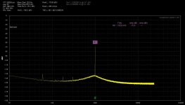
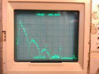
The first plot was the QA400 ADC. KH4400 into the ADC with the system tied to the charger for the laptop. The second was the output of the QA400. Its DAC output into a 7L5. Input set to 1 MOhm. I only plotted to 1 MHz because there was nothing of interest above 1 MHz. I don't see the nasties. Am I lucky? Is there something I'm missing?
Adding 20dB of gain and using the QA's add gain feature to scale the plot. The QA is not quite as good as the EMU0204 but comparable.
I don't really see a problem here.
hi --- are you using a notch filter?
-RM

The first plot was the QA400 ADC. KH4400 into the ADC with the system tied to the charger for the laptop. The second was the output of the QA400. Its DAC output into a 7L5. Input set to 1 MOhm. I only plotted to 1 MHz because there was nothing of interest above 1 MHz. I don't see the nasties. Am I lucky? Is there something I'm missing?
Here's a run to 100MHz with the HP 3577A:
An externally hosted image should be here but it was not working when we last tested it.
In normal operation, a 20dB attenuator is employed in the 3577A.
hi --- are you using a notch filter?
-RM
Yes there's a notch.
I keep the generator turned off and use an external osc.
I was never a fan of the Gen.
Last edited:
Still nothing abnormal-
http://www.ti.com/lit/an/slaa313/slaa313.pdf
http://www.ti.com/lit/an/slea048/slea048.pdf
http://www.wolfsonmicro.com/documents/uploads/misc/en/Design_Eval_AudioDAC_Whitepaper.pdf (pg 4)
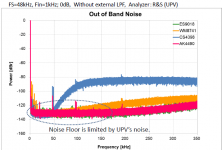
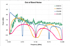
Look at the attached pictures. The Crystal DAC has the highest noise at the edge of the band. That's what you are seeing. Thats their noise shaping. I'm told that the noise shaping on the ESS is "noisy", always changing, unlike the others in this plot. I suspect its because its not synced to the incoming data.
These are generic and will be different with different sample rates.
http://www.ti.com/lit/an/slaa313/slaa313.pdf
http://www.ti.com/lit/an/slea048/slea048.pdf
http://www.wolfsonmicro.com/documents/uploads/misc/en/Design_Eval_AudioDAC_Whitepaper.pdf (pg 4)
Look at the attached pictures. The Crystal DAC has the highest noise at the edge of the band. That's what you are seeing. Thats their noise shaping. I'm told that the noise shaping on the ESS is "noisy", always changing, unlike the others in this plot. I suspect its because its not synced to the incoming data.
These are generic and will be different with different sample rates.
Attachments
The data sheet for the CS4272 shows a differential 2 pole filter for post filtering of the output of the codec. Again there isn't enough op amps in the QA to support this. The output is used single ended not differentially. I don't know how good the filtering is with just a single output from the codec used. The dac is a switched capacitor type which are inherently noisy.
There is also a switched capacitor filter built into the dac. Without adequate filtering on the output.....
There is also a switched capacitor filter built into the dac. Without adequate filtering on the output.....
I also plugged in a 2nd QA400 that i had bought back when I couldnt get the thing to work right... it shows same affect. I dont think it causes any IM image issues with low level signals up to 20KHz source/gen.
Its strange that it is there with some QA400 and Not there in your QA400. Mine behaves as if only the screen freezes when you stop the Run..... but in the bakground it is still running.
Which version are you using --QA400 software/firmware?
THx-RNMarsh
Its strange that it is there with some QA400 and Not there in your QA400. Mine behaves as if only the screen freezes when you stop the Run..... but in the bakground it is still running.
Which version are you using --QA400 software/firmware?
THx-RNMarsh
Last edited:
I also plugged in a 2nd QA400 that i had bought back when I couldnt get the thing to work right... it shows same affect. I dont think it causes any IM image issues with low level signals up to 20KHz source/gen.
Its strange that it is there with some QA400 and Not there in your QA400. Mine behaves as if only the screen freezes when you stop the Run..... but in the bakground it is still running.
Which version are you using --QA400 software/firmware?
THx-RNMarsh
Who are you asking Rick?
The QA holds the last data packet sent when input stops. The averaging continues. I think that's what you see in the background.
Who are you asking Rick?
The QA holds the last data packet sent when input stops. The averaging continues. I think that's what you see in the background.
comment to Demian.
Davada -- I think that could be IT. But why not shown on Demian's QA400?
Thx-Richard
-60 dB test
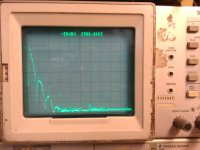
Here are two spectra, both of the QA400 running at 10 KHz -60 dB. You can see some of the aliasing, but most important is the noise peaking at 100 KHz falling on both sides. It looks like the Crystal spectrum I posted above.
When I stopped the test signal it stopped. Seems completely normal to me.
Here are two spectra, both of the QA400 running at 10 KHz -60 dB. You can see some of the aliasing, but most important is the noise peaking at 100 KHz falling on both sides. It looks like the Crystal spectrum I posted above.
When I stopped the test signal it stopped. Seems completely normal to me.
Attachments
I had damaged the front end of my AP, and it's back and calibrated:
0dBV for both with the QA400 shifted up to 1.1kHz, the AP at 1.0kHz
Both at 1kHz -60dBV:
0dBV for both with the QA400 shifted up to 1.1kHz, the AP at 1.0kHz
An externally hosted image should be here but it was not working when we last tested it.
Both at 1kHz -60dBV:
An externally hosted image should be here but it was not working when we last tested it.
- Home
- Design & Build
- Equipment & Tools
- QuantAsylum QA400 and QA401