You know, I have a spare board with that circuitry. I'm itching to add a small micro and turn it into an autoranging sound card interface...
jan
I've got three boards coming from OSH Park. That's there minimum. Two more than I need.
It's USB OTG. PIC18F2455 setup with isolated I/O channels. Two ports of isolated SPI. It's set up to drive Microchips SPI I/O expanders which could give you up to 16 or 32 outputs depending on which expander IC is used. I've installed a USB boot loader so firmware programming is done though USB. It wouldn't take much to customize one for your purposes with a simple graphical interface to run the whole thing. This is already done for my purposes. If you're interested in one I would just need to know what your needs are.
The expander(s) go on there own board. That I would leave up to you.
They are available in DIP and SOIC.
The existing linear circuitry in the QA400 seems to run off a very low voltage -- perhaps 2.4V. I didn't probe around a lot as the fluke leads aren't really designed for SMTs.
Since we're dealing with an instrument with limited bandwidth (the AP will perform FFT out to 103kHz, the QA is 20kHz) it might be useful to transformer couple the outputs to protect them from DC -- AP does this. Then you could also select the output impedance with insertion of a resistor. The outputs of the QA400 aren't happy with low-ish "Z" loads and a compound amplifier around the LME49710/LME49600 would help.
The inputs really need protection. If you're going to build a new low noise, low distortion front end, a low noise power supply has to go with it, especially if clamp diodes are going to be used. I liked the Boonton 1120 front end's protection scheme, but no longer have access to that manual.
As I've blown up many front ends measuring power supply noise and Zout, I would suggest a "sacrificial" socketed opamp, clamp diodes, a bit of RFI protection (and in my case, the ability to "pre-charge" the input coupling capacitor.)
(I note that new Jung regulator boards are available from the Diyaudio store.)
? I can get the QA400 to FFT to just shy of 100 KHz in 192KHz sample mode.
I have not seen issues from supply noise in the QA400, just ground issues.
As shipped the QA400 is great for mobile electronics. I have used it with mobile phones and iPods with excellent results. (Battery powered so no ground issues.) Its not really suitable for higher voltage stuff without some external help. The reason for the interface board.
I have the gen 2 design finished (if my tech comes through today) and I'll post it. I borrowed heavily from the Boonton 1120. The input protection circuit of the Boonton limits its SNR. Its also only useful with the autoranging. The concept I used was probes to scale the input appropriate to what you are measuring. This simplifies the protection requirements. Also reduces the number of adapters you need to juggle.
The gen 1 design had too high a noise/distortion floor for this application. Levels over 3V work fine. below and the internal noise dominates. Running a balanced audio signal at +10 to +20 its great. Also used socketed devices. But for the performance you can get from the box that interface is a limiter. The next gen should be way better in that respect. It will be a few weeks before I have the first sample assembled.
Jan-
The 1120 board has most of the autorange stuff on it already. A simple up-down counter responding to the comparator on the board may be enough. It still will limit the performance with its noise issues. Jumpering the 10K resistors at the input helps a lot. There are other tricks as you know. Unfortunately none of the software available relates to the autoranging so you lose info on the input signal level.
On closer inspection of the 1120 input board U1 and U2 are set up as data latches.
The comparator acts like a protective circuit by clearing U1 at +/- 10V peak detection at TP4 and TP6. To drive the relays you only need to setup the data inputs to the six latches and strobe the clock. Many simple ways to do this.
The comparator acts like a protective circuit by clearing U1 at +/- 10V peak detection at TP4 and TP6. To drive the relays you only need to setup the data inputs to the six latches and strobe the clock. Many simple ways to do this.
Jan-
The 1120 board has most of the autorange stuff on it already. A simple up-down counter responding to the comparator on the board may be enough. It still will limit the performance with its noise issues. Jumpering the 10K resistors at the input helps a lot. There are other tricks as you know. Unfortunately none of the software available relates to the autoranging so you lose info on the input signal level.
Was just looking at it and it seems that the Boonton input/autoranging board is really stand-alone. The digital outputs that go off-board are only necessary to tell the rest of the system what the attenuation setting is so it can correctly display the level.
I can see that the window comparators for the CM and SE DM outputs clock the counters that drive the relays. Not sure how it ranges back up. The window comparator limits are set at +/-10V so the target output of the board seems somewhere up to 7V RMS, which is too hot for most sound cards. But that's easily fixed.
Edit: David we xposted. I will check your view.
Edit2: Yes David, you're right, the comparators are only for overrange.
jan
Last edited:
But how are they auto detecting the range? Or maybe they are not. The data sent to the latches is predictable by design, Maybe Boonton just displays the set range.
There's also gain ranging further downstream, on the filter and notch boards. I need to follow the signal flow.
Jan
I think the on board stuff is part of the protection circuit. It only needs to go one way and being local no CPU action required. The 1120 seems to keep the output of the board between about 2V and about 5V. Thats probably controlled by the micro. You could change the sensitivity of the comparators and use an updown counter with a trigger to do the autorange. There may be a simple circuit in an early DVM you could lift. I could not find anything in my manual collection however/
Maybe look at some of the Fluke stuff for auto ranging.
The principle isn't hard, a couple of window comparators and drive the relays to ramp gain up or down. It's just finding the time to attack it ...

Jan
The linear circuitry of the QA400 runs off a single ended 10V which is split by the Vcom reference of the codec.
So they have an SMPS converter in there?
QA400 ADC FFT
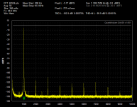
Here is what I'm getting with KH4400 to QA400, 1 KHz at .7V with the laptop connected to the charger. It seems pretty clean
Here is what I'm getting with KH4400 to QA400, 1 KHz at .7V with the laptop connected to the charger. It seems pretty clean
Attachments
OK.
The 100KHz noise is only on the QA400 signal generator output. If you use the KH for a source, you wont see anything.
The PC has the USB's DC voltage (0v) tied to chassis common. The QA400 also has the 0v of the 5v supply connected to its chassis common. And, the shield has been connected to the 0V pin as well. Thus, there is some DC flowing in the shield... if the DC isnt clean, it'll induce noise into the data lines.... However, the data lines go into the ADC as a balanced pair, IIRC. To prevent rfi pickup maybe the shield should be open at one end.
Just need a scope on the USB power and QA400 up/down dc converter outputs to see if its running at 100KHz. More DC bypass filtering needed?
THx-RNMarsh
It's the edge of the range changes that's tricky. But I guess a healthy amount of hysteresis could fix that up.
Also set the window for upranging different than downranging - which is sort of hysteresis, I guess.
Jan
Also set the window for upranging different than downranging - which is sort of hysteresis, I guess.
Jan
That's what I meant by hysteresis. Its sort of the same. It's just easier to use that word than an entire sentence. In principle it's straight forward but it seems tricky getting it all right, aligned with the ranges. I guess one could overlap the ranges just right.
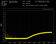
This is the first MHz of the QA400. It shows the usual noise shaping but nothing unexpected, even out to 5 MHz. The wide band spectrum analyzer is in storage so no view above 5 MHz for now.
(0-1 MHz 10 dB per division, the 1 KHz is overloading the input but that won't adffect what we are seeing.)
(0-1 MHz 10 dB per division, the 1 KHz is overloading the input but that won't adffect what we are seeing.)
Attachments
Its only on the gen output....however, you do have to load the QA400 software as well... doesnt matter if the ADC software is running/sampling or not.... just load the software and the 100KHz noise will appear.
Just connecting to the QA400 output will not produce the 100KHz noise. You have to load the QA400 software also..... then it will produce the 100KHz noise.
Thx-RNMarsh
Just connecting to the QA400 output will not produce the 100KHz noise. You have to load the QA400 software also..... then it will produce the 100KHz noise.
Thx-RNMarsh
Last edited:
EDIT: slight update/correction ---
After the QA400 software is loaded but before the RUN is enabled, there is no 100KHz noise on the gen. output.
Once the RUN is used/started for the first time, the noise on the gen output appears and does not go away after the RUN is stopped.
THx-RNMarsh
After the QA400 software is loaded but before the RUN is enabled, there is no 100KHz noise on the gen. output.
Once the RUN is used/started for the first time, the noise on the gen output appears and does not go away after the RUN is stopped.
THx-RNMarsh
- Home
- Design & Build
- Equipment & Tools
- QuantAsylum QA400 and QA401