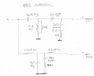
Ho hum, the crossover in the photo doesn´t resemble the Xovers in my original Heybrooks- the use of Alcaps (cobalt blue) instead of Elcaps (black with red ends) suggests it has been rebuilt and as far as I can see there is at least one Poly missing and a 10uF lytic.. Also my circuit (Post 30) doesn´t look the same although I am not the best person to express an opinion about a circuit schematic.
Ah, I missed that link. Yes, this all makes sense now. The LCR is unnecessary, but I'd say this might work well enough. Thanks, Swarky. I hate stuff unresolved.

Attachments
The circuit is correct as it stands as confirmed on another forum by an ex-employee of Heybrook. (By the way he says that all your conjections on this thread are incorrect). Although not directly involved in speakers, he believes the enigma circuit has something to do with "smoothing out the phase response".
That would be me. I spent a lot of my life between 1981 and 1984 soldering up HB2 PCBs and assembling the complete speakers.
There seems to be a bit of an upsurge in interest in HB2s at the moment, and many will need attention to their crossovers by now, so we need to make sure that not to much misinformation is being distributed.
First, a bit of history. As everyone here probably knows, Heybrook was the brainchild of Peter J Comeau and Stuart Mee. Peter and I worked for a small hifi shop in Plymouth run by one Peter Wanstall (later of JPW fame) from about 1972. PJC at the time was also freelancing as a journalist, mostly for HiFi Answers, and had been experimenting with speaker design since schooldays. Around 1975 Peter Wanstall began thinking about making speakers, so he and PJC began experimenting. I particularly remember one weird and wonderful pentagonal column creation which stood about a metre high with a 12" Richard Allen bass unit firing downwards from the bottom. Stuart Mee at the time was an enthusiastic customer of ours.
Move on to 1977 and Wanstall Hifi went spectacularly bust. Self and PJC find ourselves out of work, so he goes full-time into journalism and I go in a different direction. Neither of us is associated with PW any longer, but PJC still has the speaker itch, so he and Stuart start developing what became the HB2 in their sheds and sitting-rooms (PJC was single at the time, but I suspect Stuart's wife found it a little trying). Major influences were Stuart Tyler's Celef Monitor and, to a lesser extent the Dynaco/Scan-Dyna A25 (that influence is probably more apparent in the later HB3 and HB1, but really came to the fore 30 years later in the shape of the World Designs WD25A). Come 1979 and they've developed the new speaker into a working prototype which is generally well received by all who hear it. They rent an old barn in Ivybridge, and because Stuart lived in Heybrook Bay, a name for the new company is chosen. By November '79 production of what is now called the HB2 (Heybrook 2-way) is beginning to ramp up and I'm at a loose end, so I become the first Heybrook employee, soldering up crossovers at a bench in a stall that had recently been doing service as a milking parlour, and assembling complete speakers in the feed store. Into the spring of 1980, the barn is proving to be totally inadequate, and the HB3 is beginning to come to fruition so we move shop to a converted mushroom farm in Wembury (basically 8 Nissen huts, but a lot more room than we had before, and less chance of having to wipe snow off the cabs before assembling them). Two years on and the HB2 has been joined by the HB1, the HB3 and the TT2 (my baby), and we now have ten people beavering away turning them out by the hundred. Come 1984 and it all goes a bit pear-shaped so I leave and lose touch. The company recovers, but a few years later is bought out by our old friend PW, who now calls himself Audio Group International, incorporating JPW and Gale and a great supplier to Richer Sounds. They produce a range of thoroughly modern-looking speakers called Heybrook with natty yellow drive units. They have little to recommend them. Eventually he once again goes spectacularly bust.
The reason I'm repeating all this is to give the backgound to what I'm saying about this thread. Firstly, the crossover in the OP is absolutely as it left the factory apart from the caps,which have been replaced. No mistakes, no errors, it's a good 'un. The schematic is also spot-on. Personally, I don't understand the subtleties of cross-over design, being more of a mechanical bent, but at that time Peter and Stuart did it all by trial and error based on basic theory and endless listening tests. The little circuit in question is indeed a bit odd as was noted by many at the time and I don't understand what it does, although I believe it has some effect on phase response around the cross-over point. The point is, it doesn't really matter if theory says it shouldn't work. In practice it does, and it's a vital part of the design. If you take that circuit out, out of the window goes all the coherence and the wonderful sound-staging ability that was the whole point of the HB2, the foundaton of Heybrook's success and the kicking off point of PJC's career (not sure if he'd see it that way...). Don't fool with it. It works. If you don't believe me, take it out yourself and see what happens. Incidentally, as noted it does also mean that you can't re-jig the crossover for bi-wiring or bi-amping.
Of course, the first HB2s are now 35 years old. Most will have succumbed to bent bass units due to a huge magnet hanging on the back of a flimsy pressed-steel basket, all those foam grills that never fitted in the first place will have turned to dust and all those Elcaps will now be wildly out of spec, and will need replacing. Do that, but don't fool with the values.
Couple of other points:
Hi,
Heybrook was a small firm and probably outsourced manafacturing.
A lot of the smaller companies on the way of going out of business
took some severe liberties with QC and manafacturing standards.
One company I know had the speakers put together by the people
building the boxes, who knew absolutely nothing about electronics.
I suspect something similar.
No we didn't, or at least not while I was there.. Obviously, drive units and cross-over components were bought in. Crossover PCBs were to our design, and assembled in house (originally by me). Cabinets were made, again entirely to our design, by a cabinet maker whose name I completely forget who belonged to Monitor Audio. Assembly was again entirely in house, and QC was meticulous.
I vote for an assembly error (with no effective QC procedure), more common than you might think in boutique speakers. Don't kid yourself that all expensive speakers are individually tested - at those price points they should be, but they're not. It's entirely possible the "master" crossover the assembler was required to copy was wrong, thus many speakers would have the same mistake. It might be days - or weeks - until the error was discovered. This kind of thing really happens, especially when the original speaker designer is off-site and doesn't make frequent visits to the assembly plant.
Nope. Not an error. And we didn't work like that. Every single pair of speakers was plugged into a system and given a listening test. If you listen to the same track 20 times a day for 4 years, you very quickly learn to spot problems, especially when the "original speaker designer" has his desk in the same room. The listening test was more than adequate for catching wiring and crossover assembly errors, of which there were a few
 . I don't ever recall a pair of speakers being returned for incorrect assembly.
We didn't have a "master crossover". I knew what it was supposed to look like....
Hi,
Yes well thanks for nothing. The circuit may be as intended but its
still wrong / poor in many respects which are not conjectures they
are facts. Not only does the 560R LCR do absolutely nothing useful
the L used with the 560R is a ludicrously inappropriate type.
The x/o is a mess, and stinks of shoddy design / manufacturing .....
And clueless employees / ex-employees .....
rgds, sreten.
The reception received by the HB2 was universally positive. It sounded bloody good and it still does, for two main reasons. First was the rear-firing friction-loaded port which gave it a decent bottom end. Second was the choice of drivers, along with the crossover design. Two blokes with brilliant analytical skills but little in the way of intrumentation put two years of their lives into getting it how they wanted, and succeeded in making a speaker which was a step ahead of anything around at the time, so in what way is it "wrong"? It worked, and it worked really, really well. If that's shoddy design, I'm all for it. As for shoddy assembly and clueless ex-employees, I couldn't possibly comment....
Last edited:
Hi, I'm coming a little late to this party because I've only just found this thread by accident while looking for something else.
As it turns out everything shanewhite says is true and I thank him for his diligence in re-constructing the company history in a potted precis.
Now, that peculiar bridge circuit! Hah, yes it doesn't model in a circuit simulator, does it? And therein lies a peculiar effect caused by the fact that it is actually quite difficult to reproduce reality in a circuit simulator when you are dealing with gross electromechanical devices like loudspeaker drive units. These things are really very difficult to model effectively due to their mechanical distortions, which are level related, and their constantly changing impedance with frequency. Put that together with a crossover where the load reflected to the amplifier also changes dramatically with frequency and you have a whole catalogue of sonic effects which circuit simulators don't take into account.
Look, if it was that easy to design loudspeakers everyone would be putting together award winning speakers from every company every month. However we all know that doesn't happen. The number of good sounding speakers which are accurate enough to replay a wide range of music enjoyably and with realism are actually quite hard to find.
So, back to that pesky 'bridge' circuit as we called it originally. There's no apparent reason for it being there. But when we were designing the original prototypes we just felt that we were missing some integration between the drivers. Like most things in audiophile hifi, this 'bridge' circuit came about as the result of a fortuitous experiment.
It doesn't affect the measured response and, as you'd expect from the 560 Ohm resistor, it doesn't affect the impedance. But I can tell you it DOES affect the sound. Change that 560 Ohm resistor value or remove it and the coherence between the drivers subtly changes. The speakers just don't sound so coherent and the stereo image isn't so 'out of the box' without it. Similarly we tried different types of coil for the 1.45mH in series with it and they just sounded 'wrong'. Go figure!
I also noticed a comment on the 1.1uF and 15R across the tweeter as a 'Zobel' network. As pointed out these are the wrong values for a Zobel network. That's not surprising as that's not what it is. All it does is just tame a little bit of 'zing' from the Audax tweeter.
Also note the layout of the crossover PCB, the distance between the components and the odd angles of the coils. These were all part and parcel of listening to the magnetic interaction between coils and capacitors and our way of minimizing coloration due to it.
Furthermore we developed the crossover sitting on top of the cabinets, so it sounds best on the inside of the top of the cabinet or behind the tweeter, NOT behind the bass unit where most people put crossovers for ease of assembly.
Nowadays I wouldn't do it this way. There are better ways of effecting good coherence between drivers using more conventional circuit ideas. But, at the time, we didn't have the luxury of simulation software like LspCAD to help us. So we just tried things and listened. The HB2 crossover, with its odd circuit, was the result. And it worked. It worked so well that the HB2 became a landmark product at the time and put the company on the map. That the HB2 remained in production for a decade, practically unchanged, is testament to its performance and popularity.
Hello Peter, thanks for the original design procedure info. A few questions:
-Did you involve frequency response measurements as rough guide back then or it was totally balanced by ear?
-What were the exact types/brand(s) of the driver units? Polydax? Any custom differentiations you ordered in those?
-What was the measurement gear even if used for a basic check? Took it to some lab at a point?
Hi! I have just read through the thread and was very happy to see the post from PETERCOM. I have enjoyed my HB2 C then -89 and still think that there are few speakers under 2 "to match them. I have bought me a second pair and looking for more to use in a multichannel system. Most speakers available to purchase, however, have broken woofers, and Audax has stopped manufacturing the original ones. Has anyone a suggestion of suitable replacement element?
/Lars-Ake
/Lars-Ake
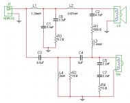
I must have missed the interesting updates on the Heybrook HB2 Classic from people involved in it's production. It's not a million miles away from the Robin Marshall Audiomaster MLS4, and had reflex 6" Audax bextrene bass and a 1" Audax soft dome tweeter.
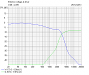
This is a Third Order Butterworth filter AFAIK, quite the vogue at the time, rather than the currently fashionable LR4. Very flat power delivery being its strength.
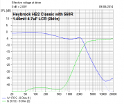
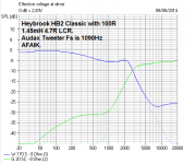
Of course, the mystery was the odd 560R LCR connecting the two drivers. It DOES actually DO something, but does a lot more with a 100R resistor. In fact it all then looks terribly familiar if you know the whole crossover oeuvre.
What an artist might call an "interesting failure", if he's honest.
This is a Third Order Butterworth filter AFAIK, quite the vogue at the time, rather than the currently fashionable LR4. Very flat power delivery being its strength.
Of course, the mystery was the odd 560R LCR connecting the two drivers. It DOES actually DO something, but does a lot more with a 100R resistor. In fact it all then looks terribly familiar if you know the whole crossover oeuvre.
What an artist might call an "interesting failure", if he's honest.
Attachments

Again we have this very strange idea that a oudspeaker that sounded better than it's peers, was commercially successful, well reviewed and still sounds good thirty years later is in some way a failure or a mistake simply because it has an unusual design feature in its crossover. I don't get it. If theory and pre-coceptions say the design won't work when in practice it works very well, it's not the design that's at fault, it's the theory and preconceptions.
It's a good speaker. There's nothing wrong wiith it. It works.
It's a good speaker. There's nothing wrong wiith it. It works.
Again we have this very strange idea that a oudspeaker that sounded better than it's peers, was commercially successful, well reviewed and still sounds good thirty years later is in some way a failure or a mistake simply because it has an unusual design feature in its crossover. I don't get it. If theory and pre-coceptions say the design won't work when in practice it works very well, it's not the design that's at fault, it's the theory and preconceptions.
It's a good speaker. There's nothing wrong wiith it. It works.
Good post

Shane, you took me the wrong way there. My (constructive) criticism is that Peter Comeau didn't go far enough with that crossover!Again we have this very strange idea that a oudspeaker that sounded better than it's peers, was commercially successful, well reviewed and still sounds good thirty years later is in some way a failure or a mistake simply because it has an unusual design feature in its crossover. I don't get it. If theory and pre-coceptions say the design won't work when in practice it works very well, it's not the design that's at fault, it's the theory and preconceptions.
It's a good speaker. There's nothing wrong wiith it. It works.
The weird looking LCR and the 15R damping on the tweeter filter was actually quite inspired.
I said I'd seen that electrical response before. In KEF acoustic butterworth notching for tweeter Fs, the regular 5kHz notch for a 6" woofer, and in my own experiments with series filters.
6" bass and 1" tweeter is quite hard. This is BW3 improved, and I enjoyed looking at your handiwork. I think some modern LR2 and LR4 designers could learn a thing or two from the Heybrook HB2 Classic. It was a sort of Golden Age of the complex crossover. Amazing that it was all done with Smith Charts and slide rules and a lot of mental arithmetic. Respect.
Attachments

Sorry If I mis-understood your "interesting failure" remark. It's just that
the HB2 wasn't by any definition a failure. Despite, ot maybe perhaps
because of, it's unusual crossover, it was deservedly a resounding success!
Hi,
It sold well, but thats no excuse for shambolic quality control,
or just very badly designed crossovers, or both, take your pick.
That it sold well was largely on the back of good reviews *
rather than discernment by the buyers, and its true to
say given the nonsense in this thread about the x/o
being right, it isn't, but hard to say the exact case,
the care of customer responsibilty wan't uppermost.
rgds, sreten.
* Probably prototypes, not farmed out production.
At the time I've seen speakers asssembled by companies
that make the cabinets, that don't have a clue whether
they work well or not, only testing if the drivers work.
Last edited:
* Probably prototypes,
Totally wrong. Review samples were taken from production with no extra attention.
Totally wrong. All Heybrook speakers were assembled and tested in the Heybrook factory by Heybrook employees.farmed out production.
You're absolutely entitled to voice your opinions on the crossover design, although your opinions would be more valuable if you could explain how the design is detrimental to the sound. All you seem to be saying is "I can't see what this circuit does, so it must be crap. Therefore the product must be crap, and that means that the people who made it were probably crap too".
That's your opinion, and you're welcome to it, but your comments about quality control and outsourcing are just plain wrong. We did not use the manufacturing techniques that you so arrogantly assume we did. If you can't even get your basic facts right when slagging off other people's efforts and achievements, why should anyone respect your opinions?
We used to have a saying about the office sourpuss: "He may be a horrible *******, but at least he's horrible to EVERYBODY!"
Shane, it's a good crossover and a good choice of drivers. The LCR is doing no harm at all, and slightly improving phase response. And I always respected the WIREMEN who'd just patiently sit in a corner on piece-rates and do elegant and tidy wiring and soldering.
Methods in 1980 weren't too primitive either, excellent AVOmeters, a dual beam Tektronix oscilloscope for measuring input and output square wave response, and some Bruel and Kjaer white noise testing were rather revealing. I know because I started in the lab then. We also had decade boxes where you could effectively dial in any filter value you fancied and test it.
What we didn't have were computer simulations, unless a Hewlett Packard HP-67 224 step programable calculator counted, but we did have older engineers who could design AM and FM radios in their heads, and usually had a military track record in Radar and microwave techniques. You could always go to them for a bit of help. They used to call me "Three-Piece Steve", due to my penchant for waistcoats and bow ties. I think they found my callow youthful overconfidence rather funny.
Last edited:
So he's unpleasant to everyone? Must be a very sad and jaded existence if all he can find time to do is pour scorn on all and sundry. Still, takes all sorts, I suppose.
Once the HB2 was up and running and there was a bit of cashflow going on, one of the more intriguing tasks I was given was to build an anechoic chamber. Peter got hold of a B&K sweep generator and curve tracer, and from what I remember it was pretty useful down to about 200Hz. That would have been aroung the time the HB1 and the series 2 version of the HB3 were being developed. It was useful for measuring the major effects of design changes, but the final arbiter was always the mark 1 lug-hole.
Once the HB2 was up and running and there was a bit of cashflow going on, one of the more intriguing tasks I was given was to build an anechoic chamber. Peter got hold of a B&K sweep generator and curve tracer, and from what I remember it was pretty useful down to about 200Hz. That would have been aroung the time the HB1 and the series 2 version of the HB3 were being developed. It was useful for measuring the major effects of design changes, but the final arbiter was always the mark 1 lug-hole.
Resistor in HB2 Crossover has run very hot...
My apologies for attempting to reopen such an old thread but I am in the process of recapping my father's HB2s and have come across a bit of a puzzler.
The 15 ohm resistor R2 in one of the crossover has obviously been running very hot as the PCB underneath it is substantially charred. The other crossover shows no sign of excess heat.
I don't pretend to really understand this circuit, particularly after digesting this thread!
Could a burnt out tweeter voice coil have caused this? If not has anyone any ideas what could have happened here.
As part of the renovation I have replaced both Audax tweeter voice coils/diaphragms
Thanks in anticiapation
Attachments
Last edited:
I'm no speaker expert but a couple of thoughts...
1/ Could the amplifier it was used with have a problem such as high frequency oscillation/instability ? That could cause a very high dissipation in the resistor.
2/ Make sure that the other passives around the resistor are OK. L4 should have continuity when tested out of circuit, so make sure its not open. If C3 were short circuit then it would stress the resistor.
I'm no speaker expert but a couple of thoughts...
1/ Could the amplifier it was used with have a problem such as high frequency oscillation/instability ? That could cause a very high dissipation in the resistor.
2/ Make sure that the other passives around the resistor are OK. L4 should have continuity when tested out of circuit, so make sure its not open. If C3 were short circuit then it would stress the resistor.
It is certainly possible that it could have been exposed to high frequency oscillation as these speakers have been used with many amps over the years.
L4 and C3 are good
Thanks for your comments .. my concern is that I don't want to blow the new tweeter voice coils... the amplifier I will be using is totally stable and will not oscillate
- Home
- Loudspeakers
- Multi-Way
- Q on Heybrook HB2 XO