I vote for an assembly error (with no effective QC procedure), more common than you might think in boutique speakers. Don't kid yourself that all expensive speakers are individually tested - at those price points they should be, but they're not. It's entirely possible the "master" crossover the assembler was required to copy was wrong, thus many speakers would have the same mistake. It might be days - or weeks - until the error was discovered. This kind of thing really happens, especially when the original speaker designer is off-site and doesn't make frequent visits to the assembly plant.
Shift the 560 ohms to 5.6 ohm, and reconnect the low side of L3 (1.4mHy) to ground, and the circuit becomes a pretty straightforward parallel crossover. Two stupid mistakes, and the crossover still works, but the tweeter notch filter disappears and the tweeter distortion goes up. If you corrected the 5.6 ohms, but left the notch filter misconnected, the wacko response might be obvious enough to notice on the standard FR test (if any was done on the production speakers).
Shift the 560 ohms to 5.6 ohm, and reconnect the low side of L3 (1.4mHy) to ground, and the circuit becomes a pretty straightforward parallel crossover. Two stupid mistakes, and the crossover still works, but the tweeter notch filter disappears and the tweeter distortion goes up. If you corrected the 5.6 ohms, but left the notch filter misconnected, the wacko response might be obvious enough to notice on the standard FR test (if any was done on the production speakers).
No, I haven't made any modifications to the XO. These speakers are currently in my upstairs office.
I purchased them from PAC in Millburn NJ perhaps 15 or more years ago. They don't have the lettering at the bottom of the box as shown on yours -- but they did come with dedicated stands.
I purchased them from PAC in Millburn NJ perhaps 15 or more years ago. They don't have the lettering at the bottom of the box as shown on yours -- but they did come with dedicated stands.
There was a similar connection between the woofer and tweeter networks in some Polk speakers in the late 1970s. Can't remember if it was the 11 or the 12, but it was one of the models that was better than the Monitor 5-7-10 series, but not the SDA with the built-in Dynaquad effect.
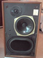
The circuit trace is correct. Mine are exactly the same. I am just overhauling them after 15 -20 years as Audax are selling the HD12x905 tweeter voice coils again. Will change the electrolytics and little else.
At the time I consulted Heybrook to se if I could split the Xover so as to biwire. I was told that the treble and bass circuits were not to be separated.
At the time I consulted Heybrook to se if I could split the Xover so as to biwire. I was told that the treble and bass circuits were not to be separated.
You are saying you find the OP's, jackinnj's circuit?
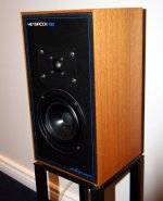
BTW, Is this the Yellow kevlar bassed HB2, or the black (Polycone?) version or a paper cone? I see several different looking HB2's on the net.
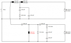
I can't help noticing the L4 coil looks nearer 0.2mH than 2mH, which makes this a third order treble, rather than near first order.
As far as I can see, Heybrook have been doing a bit of quick and dirty crossover modding for different drivers and models. The tiny 1W 560 ohm resistance takes the LCR out of circuit, but it would make more sense at 4.7uF, 0.2mH and about 2.2 ohms anyway if it was a bass shunt. The mystery 2kHz notch may have been originally there for some polycone nasty on a previous model.
My best guess of the circuit is below. I could simplify that a lot, I reckon. Or design it with an LCR bass notch.
An externally hosted image should be here but it was not working when we last tested it.
An externally hosted image should be here but it was not working when we last tested it.
BTW, Is this the Yellow kevlar bassed HB2, or the black (Polycone?) version or a paper cone? I see several different looking HB2's on the net.
I can't help noticing the L4 coil looks nearer 0.2mH than 2mH, which makes this a third order treble, rather than near first order.
As far as I can see, Heybrook have been doing a bit of quick and dirty crossover modding for different drivers and models. The tiny 1W 560 ohm resistance takes the LCR out of circuit, but it would make more sense at 4.7uF, 0.2mH and about 2.2 ohms anyway if it was a bass shunt. The mystery 2kHz notch may have been originally there for some polycone nasty on a previous model.
My best guess of the circuit is below. I could simplify that a lot, I reckon. Or design it with an LCR bass notch.
Attachments
Last edited:
Sorry, my HB2s are the original versions with a bextrene mid/woofer and one Audax HD12x925A tweeter. I haven´t been able to check the coils but the circuit is this one :
HB2C.jpg Photo by VantheManspeakers | Photobucket
The Elcaps are Low loss electrolytics which have drifted from their values and I will be changing for Alcap drop-ins from Falcon. There are 3 polys which I will change for Solens. The rest I will leave alone.
HB2C.jpg Photo by VantheManspeakers | Photobucket
The Elcaps are Low loss electrolytics which have drifted from their values and I will be changing for Alcap drop-ins from Falcon. There are 3 polys which I will change for Solens. The rest I will leave alone.
BTW, Is this the Yellow kevlar bassed HB2, or the black (Polycone?)
version or a paper cone? I see several different looking HB2's on the net.
Hi,
Its a Audax HD17 bextrene coned unit, came in two magnet
sizes, typical at the time for bassmid drivers. Smaller magnet
for sealed and bigger magnet for vented was the intention.
Bextrene units typically had midrange peaks that
needed to be addressed in the x/o somehow.
I missed that very odd treble inductor value at the time.
The x/o is a real mess, who knows what was going on.
rgds, sreten.
The circuit is correct as it stands as confirmed on another forum by an ex-employee of Heybrook. (By the way he says that all your conjections on this thread are incorrect). Although not directly involved in speakers, he believes the enigma circuit has something to do with "smoothing out the phase response".
Last edited:
Well...MAYBE...The circuit is correct as it stands as confirmed on another forum by an ex-employee of Heybrook. (By the way he says that all your conjections on this thread are incorrect). Although not directly involved in speakers, he believes the enigma circuit has something to do with "smoothing out the phase response".

I can only tell you the LCR with 560R in it does next to nothing to ANYTHING! I modelled it.
An externally hosted image should be here but it was not working when we last tested it.
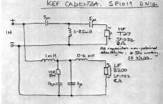
The LCR with about 10R in it, connected to earth, might tame a Bextrene-type 2kHz midrange peak, which was Lynn Olson's idea. Now that man is pretty good, I tell you.
There is still doubt in my mind whether the tweeter filter coil is 2mH or nearer 0.2mH. Both work after a fashion, but the smaller one takes the filter steeper. Can't remember if phase is affected offhand.
Hi Steve,
When I wrote "your conjections", he was referring to the thread as a whole.
Not to worry, I just hope that , once tidied up, my HB2s sound as good as I remember them so many years ago. Who knows, maybe one day Peter will come out of hiding in China and spill the beans, if there are any to be spilt.
All the best,
Chris
sreten is indeed looking good on his Audax HD 17 call. Whether you have the big magnet reflex or small magnet closed box version is for you to confirm.
Google Audax HD 17 images for more detail.
But those of us who like this game have seen this sort of thing before. Here's the 8" B200 bextrene ABR/reflex KEF Cadenza. Not a million miles away, I think you'll agree.
Google Audax HD 17 images for more detail.
But those of us who like this game have seen this sort of thing before. Here's the 8" B200 bextrene ABR/reflex KEF Cadenza. Not a million miles away, I think you'll agree.
Attachments
sreten is indeed looking good on his Audax HD 17 call. Whether you have the big magnet reflex or small magnet closed box version is for you to confirm.
There were also two-layer and four-layer voice coil versions, available with either magnet. And one with a cast basket.
The circuit is correct as it stands as confirmed on another forum by
an ex-employee of Heybrook. (By the way he says that all your
conjections on this thread are incorrect). Although not directly
involved in speakers, he believes the enigma circuit has
something to do with "smoothing out the phase response".
Hi,
Yes well thanks for nothing. The circuit may be as intended but its
still wrong / poor in many respects which are not conjectures they
are facts. Not only does the 560R LCR do absolutely nothing useful
the L used with the 560R is a ludicrously inappropriate type.
The x/o is a mess, and stinks of shoddy design / manufacturing .....
And clueless employees / ex-employees .....
rgds, sreten.
Last edited:
Hi,
As I made clear in the previous post, that was a collective "your" conjectures I/he referred to. Nothing personal. I don´t doubt you are technically correct and I guess this is a prime example of subjective success over objective.
As you may or may not know this speaker was extremely well received in its day and people still speak very fondly of it. Not important but I have even seen it well placed in a typically non-scientific forum results in a vote to find the top 25 speakers ever made !
We can´t all have been deaf so maybe simulations are not the be all and end all and if the 560R does nothing it all and doesn´t affect the sound, it just meant lower Heybrook profits.
Chris
Ah, the wrath of sreten falls on Heybrook!
But really, we aren't getting very far on this. It's time for some proper analysis.
See, we KNOW that LCR with the 560R might as well not be there. The 15R + 2X 2.2uF is actually a 15R +1uF Zobel, which actually does almost nothing either, because it has no series filter resistance to work with.
But it's that little (L4?) nylon bobbin air coil that is bothering me. Like I say, 0.2mH or thereabouts would make sense for a third order filter. I'm also guessing the tweeter could be wired in reverse polarity, but that's a guess.
But really, we aren't getting very far on this. It's time for some proper analysis.
An externally hosted image should be here but it was not working when we last tested it.
An externally hosted image should be here but it was not working when we last tested it.
See, we KNOW that LCR with the 560R might as well not be there. The 15R + 2X 2.2uF is actually a 15R +1uF Zobel, which actually does almost nothing either, because it has no series filter resistance to work with.
But it's that little (L4?) nylon bobbin air coil that is bothering me. Like I say, 0.2mH or thereabouts would make sense for a third order filter. I'm also guessing the tweeter could be wired in reverse polarity, but that's a guess.
Ho hum, the crossover in the photo doesn´t resemble the Xovers in my original Heybrooks- the use of Alcaps (cobalt blue) instead of Elcaps (black with red ends) suggests it has been rebuilt and as far as I can see there is at least one Poly missing and a 10uF lytic.. Also my circuit (Post 30) doesn´t look the same although I am not the best person to express an opinion about a circuit schematic.
- Home
- Loudspeakers
- Multi-Way
- Q on Heybrook HB2 XO