![IMG_4314[1].jpg](/community/data/attachments/536/536066-867e8cf6590fcf7e82e13b580f12e926.jpg)
![IMG_4319[1].JPG](/community/data/attachments/536/536071-ef58e3be1d2df2c9886ad01d59901cae.jpg)
I'll see instructions with my DMM. If nothing else, I will use as is, hate to not have them with your matching, knowing parts are there, plus I will learn something if nothing else!
I see from google search there is much info, even if instructions are elusive...on with the build.
Russellc
I see from google search there is much info, even if instructions are elusive...on with the build.
Russellc
Zenmod, another question on resistors. It concerns Shunty R3, R3a, R6, R6a.
The chart in your cookbook call for 150 ohm to 240 ohms. In the Pumpkin I see a similar deal with R9, R10, R14, R15, R19. what determines the value in Shunty? In Pumpkin? (havent looked at Pumpkin that hard yet, still on shunty)
I am also a little confused with the circuit diagram showing red and green resistors?
thanks,
Russellc
Does the range of all these resistors mean "anything" in that range one has on hand, or is there some criteria in value selection? both numbers given and red and greenies? I should have asked question better, it selection of the values that I am asking about.
Thanks again,
Russellc
Thanks again,
Russellc
Last edited:
shunty progress... xformer connection question
After finishing up some intervening projects, I had time to solder the shunty boards, just need to get the heatsink mounting set (awaiting a few parts needed for that). Still a significant list of things to source, but nice to see some results. I'll probably get a dummy load so that I can test these, I think I'd like to know all is good before the Pumpkin build.
I'd like to double check how to wire transformers - I picked up 4 of the Mercury Magnetics TA-110W from ApexJr, so 2 per shunty. Each one has a 0 - 43V secondary, so to wire 2 together, I would wire the primaries in parallel and the secondaries in series, right?
Tod
After finishing up some intervening projects, I had time to solder the shunty boards, just need to get the heatsink mounting set (awaiting a few parts needed for that). Still a significant list of things to source, but nice to see some results. I'll probably get a dummy load so that I can test these, I think I'd like to know all is good before the Pumpkin build.
I'd like to double check how to wire transformers - I picked up 4 of the Mercury Magnetics TA-110W from ApexJr, so 2 per shunty. Each one has a 0 - 43V secondary, so to wire 2 together, I would wire the primaries in parallel and the secondaries in series, right?
An externally hosted image should be here but it was not working when we last tested it.
Tod
........
I'd like to double check how to wire transformers - I picked up 4 of the Mercury Magnetics TA-110W from ApexJr, so 2 per shunty. Each one has a 0 - 43V secondary, so to wire 2 together, I would wire the primaries in parallel and the secondaries in series, right?
.....
Tod
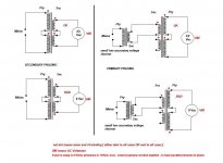
prior to connecting secndaries to pcb , you must correctly phase them
as you said - primaries in parallel , secondaries in series
measure with Vac meter opposite secondary ends ; if you have double voltage then phase is ok ; if you read almost 0Vac , phase is wrong (in which case just swap leads of one secondary and retest)
when you're sure of phasing , solder to pcb
attached pic made for solo xformer , but same logic applies ...... once when you wire pry. in parallel and connect secondaries in any way , that's practically one system
Attachments
prior to connecting secndaries to pcb , you must correctly phase them
as you said - primaries in parallel , secondaries in series
measure with Vac meter opposite secondary ends ; if you have double voltage then phase is ok ; if you read almost 0Vac , phase is wrong (in which case just swap leads of one secondary and retest)
when you're sure of phasing , solder to pcb
attached pic made for solo xformer , but same logic applies ...... once when you wire pry. in parallel and connect secondaries in any way , that's practically one system
Got it. Thanks for the sanity check, Zen Mod!
Tod
Hi!
Many years ago Zen Mod supported me with Pumpkin Shunty PCB's and key-parts.
Now I start to dig at my electronic collection (my wife says: garbage collection) with strong final decision to make Pumpkin Shunty ready. I am retired almost one year and it's perfect time to finalize many things I began before retirement.
Long time no see...I would like to cordially say hello to Mr Nelson Pass and all diyAudio Members, especially Zen Mod 'Choky', James Hill, Peter Daniel and Jacco Vermeulen! Do you remember me?
F-4 still works great.
Best Regards,
Andrzej
Last edited:

matching mosfets for Pumpkin
Hi Zen Mod -
I'm ordering parts for the Pumpkin boards, and I just realized I'm going to have to match Q5-Q7 (IRF9510) and Q6-Q8 (IRF510). I've never done this before, so a couple of ?s:
- What is a good number of each to buy and test to get the 2 matched pairs needed?
- I've read the Pass article on matching (https://www.passdiy.com/pdf/matching.pdf), so my plan is to use a Shunty as the power supply, but what current am I aiming for? Or is there a better way to go about this?
Any clues appreciated!
Tod

- Status
- This old topic is closed. If you want to reopen this topic, contact a moderator using the "Report Post" button.
- Home
- Amplifiers
- Pass Labs
- Pumpkin Shunty begins....