Zen Mod said:
there is no need to thank me ........ and to make me blush ( even if that is pretty impossible)
I was interested in exact difference (sound etc. ) between these two sides of same coin...... hehe - even if mine is pretty gray comparing it to certain complexity of chips ............ thinking about difference in efforts to make one or another and final results ....
in any case - if these chippy dreks are made by Papa's pattie pattie , they can't be bad ..... so easily
btw - I can't find exact schmtc of twisted X without too much trouble ..... (seems that today search func and me aren't in good relation)
have you linkie to exact post ............
hehe - I can bother ya - seems that your shoulder is certainly better - more than one post in a week
Yep, shoulder is pretty good, so I am posting again using too much time on PC, so shoulder is gonna be bad again

There is all reason to thank you!! You have been giving more to the DIYaudio community than anyone else (except Mr P. ofcourse) Babbelfish & Pumpkin, together with a never ending will to help out!! DIYaudio would be a poor place, without you
Here is the TXD manual made by the two great pears:
http://www.twistedpearaudio.com/docs/txd/txd-doc.pdf
For a chip, I can assure that it sounds just great! I was pretty surprised to find out!
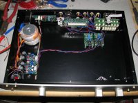
Oh, and here is a piccy of the mess, look at them small TXD boards:
Attachments
Manu said:Steen, Thanks, but I have to think a little bit about...
(You mean that said input is then always RCA?, definitively non-XLR, nevermore...)
What you says about Pumpkin is absolutely what I expect from this Serb-Jewel.
Peanuts butter and cevapi.
I can't wait to finish mine...
Its not even difficult, when you look at it the right way
Imagine this scenario: You have balanced inputs and single ended inputs! 2 inputs are reserved for balanced signals so they are left untouched!! Input #1and#2 are reserved for that! Now #3 to #6 are supposed to be single ended inputs (SE) So those will need to have the -IN grounded! Follow me so far?? Well, in case of the Darwin running balanced, there is 3 connections for each channel: + - and GND. What I did was to connect (short) the -IN of input 3-6 to GND right at the Darwins input selection!! You could do the excact same thing with a normal input selector with 4 decks....Steen.
steenoe said:
Yep, shoulder is pretty good, so I am posting again using too much time on PC, so shoulder is gonna be bad again
Oh, and here is a piccy of the mess, look at them small TXD boards:
after that post of yours , only I can is to crawl under greatest rock I can find , for at least few dayzzzzzzzzzzzzzzzzz
just one thing before that (crawling ) - what's easiest way to find few these chipsies for playin' purposes ........ ?
(I'll not mention how that thingie will work even with plain simple shunt reg ........
)Zen Mod said:
after that post of yours , only I can is to crawl under greatest rock I can find , for at least few dayzzzzzzzzzzzzzzzzz
just one thing before that (crawling ) - what's easiest way to find few these chipsies for playin' purposes ........ ?
(I'll not mention how that thingie will work even with plain simple shunt reg ........
No reason to hide under rock...
I am sure a lot of folks around here says the same There is no easy way of finding those chips, I guess... National Semi more ore less shut down on samples! (Chipamp anyone??)
I have some that I bought from Digikey. I would be more than happy to send you a few of them
Wont cost you a dime They are sort of SMD, so be warned ZM - from under the rock
you must tick "quote" field and try later to not delete these bracketed parts :
[ QUOTE ] [ i ] Originally posted by Manu [ / i ] [ B ] in front , and
[ / B ] [ / QUOTE ] on end of post you are quoting
being a professor is somewhat ......... something
I know that - my better half was/is professor , beside other things
Manu said:..........
Manu
Quoting is creavivity
you must tick "quote" field and try later to not delete these bracketed parts :
[ QUOTE ] [ i ] Originally posted by Manu [ / i ] [ B ] in front , and
[ / B ] [ / QUOTE ] on end of post you are quoting
being a professor is somewhat ......... something
I know that - my better half was/is professor , beside other things
steenoe said:
...........
I have some that I bought from Digikey. I would be more than happy to send you a few of them
that will be more than welcome - as soon you receive substitution for magically vanished pcb from Rovsing's drawer ........
just curious - how much they costed at digikey?
are they still available ?
Zen Mod said:
that will be more than welcome - as soon you receive substitution for magically vanished pcb from Rovsing's drawer ........
just curious - how much they costed at digikey?
are they still available ?
He-he, Rovsing never found out what happened
The poor chap is way too slow Besides that, he fart too much.They cost in the neighbourhood of 4-5 USD as far as I recall... I will check it out.
Here ya' go:
http://search.digikey.com/scripts/DkSearch/dksus.dll?Cat=2556125;keywords=ths4131
Prices without VAT and whatever....Usually adds up to a sigificant amount.......
http://search.digikey.com/scripts/DkSearch/dksus.dll?Cat=2556125;keywords=ths4131
Prices without VAT and whatever....Usually adds up to a sigificant amount.......
jazz said:Hey,
thanks Zen Mod. Figured as much, already tried 1k5. Guess 3k's next...
grtz
joris
nono
open that schmtc with paint , or whatever - and give us few measured values , drawn on same schmtc
if you have no pmpy schm for that - here it is:
edit:
which exactly 2SK170 you use - BL or V suffix?
Attachments
jazz said:Hi
as ordered schematic with voltage measurements.
grtz
Joris
edit: sk170 GR (sorry junkbox)
in that case - R7 and R8 increase to 1k3
goal is to have no more than 3 to 3,5mA through each GR 2SKs
you have problem with led string - which needs 5mA for proper operation
if you can't set R24 for needed 5mA through R23,R25,Q11,R24,led string chain......... than use plain bjt critter instead of Q11 - C up,B down , 130- 140 ohms as R24 - between E and B ; that way you must have ~ 5mA through biasing chain
regarding 3mA through each side of LTP .......... increase R22 to 140~150 E
jazz said:Hi Zen Mod,
Thanks for the advice. Ok gr version takes to much conversion, wanna stay close to your circuit.
For now I'll just double fets, with extra 1-10R in source should provide current sharing and hence compliance with 7 ma per halve of LTP right? Is just to get to grips with the circuit and setting procedures. I'll figure out how to get ccs in led bias string to behave.
I'll see if i can order j309 somehow. local shops say they don't know them, but farnell has em.
thanks
Joris
ps ccs in bias string is using 10x trimmer for r24, i figured the changes would require something like that.
I have no objection .......
anyway - I choose J309/310 because is :
- dirt cheap
- widely available
- more than good enough for purpose
jazz said:Hi, just fiy...
Up and running, nice and promising. Change back to 309 gave some offsett so a little matching left to do.
Now to put it in to a nice box and it seems i've got a new gadget. Thanks for the circuit and support.
cheers,
Joris
did ya hear it?
what PSU you are using ?
Hi,
Yup listening to it now, Beef running (music, not the beast). No fair comparison to the fvp5, but fun. FVP is tweaked with components and pumpkin uses only cheap standard comps.
Yet Pumpkin ceraintly has tapping factor as steenoe says, it's musical and grasps the fun of the artist when present. Also bass is very good. This is special since i normally use extra sub with the fvp (schematic for sub from ESP in luxman reciever and AR3's, SF concertino's as mains). Pumpkin has to do without sub for now.
PSU is amplimo trafo (2X115V/0.22A parallel), rc filter (1R/2200U/100V, rubycon standard), LC filter (10H/100R/200ma, 4700U/100V, rubycon standard - 1000U/50V, JD Standard on pcb). CCS as copied from shunty, supplying ~200ma (3R3), Shunt with tl431 and BD140/139, as per datasheet.
Edit: 2X47K from line (-, ground, +) to ground at first cap (2200u rc).
Main reason for psu layout was that i restricted myself to one eurocard size pcb. Hence all except raw psu had to be onboard, inc CCS and shunt. (After 8 years and a lot of veroboard i finally seem to be able to design a reasonable pcb, and i used this as an excersize).
Thanks again,
Joris
jazz said:Hi Zen Mod,
Sorry to disagree, but i've got every reason to thank you here. I'm not an ee (sociology) and need the circuits and knowledge of people like you to make it work. Thus your support is very much appreciated.
For speakers i use Sonus Faber concertino's (crossover modded), AR3I's for sub. Power amp is a stereo 6V6 triode strapped push-pull, ecc83 input, ecc33 kathodyne splitter, trannies robbed from lafayette224, large psu ~2000u/320V rc type per channel. Schematic from Audio&techniek by R. van Stratum, also called the PTA aka 'poor man's tube amplifier'. CDP is cambridge cd4 with NOS tda1541 dac using D1 I/V stage.
Now im really looking forward to completing my x100's, let's see how balanced is going to be. Also got a parallel project running for a Musical fidelity X-pre. let's fit an X preamp and balanced tda1543 dac inside...
regards,
Joris
Edit: forgot, psu is for stereo, both channels. I know, little left for shunt current. Will change to 300ma for total current but need new chokes and resistors for that.
well -regarding PSU - just made another one ( it probably cost you a few dimes) , and set CCS for each channel accordingly ;
MF X - I didn't understood - you wanna use case of X , or you wanna make one , or you wanna tweak one , with added DAC ?
regarding ^V^ ( lookie lookie how fun 6V6 can be typed ! ) - easy toob to drive ; you can do it better than with ECC83 ( this toob is good only as first toob in RIAA , even if I like completely different RIAA preamps with different toobz ) ......... anyway - I'm sidestepping again ... like always .....
you can have better amp - if you use just ECC81 or 12BH7 in LTP , as only and phase splitter stage , in front of 6V6s ;
that way you'll gain few things - less NFB and fewer stages .
you can try even 6SN7 in that place - and then you'll need little more gain (oohmps) from preamp ......
ps
I don't like MF ; even if I'm probably world's biggest fan of A1 ( just power amp stage, because of overall crazyness ) , their selling/construction philosophy is very questionable .......
EDIT:
- I'm not EE , either ......... building construction High School , and almost finished Metal Construction Uni .......... dunno proper Engrish names for those Schools ...........
Choky, you're gonna ring my neck
All the pumpkins goin together per the cookbook means that I have to do something different. I'm back to plan A - No shunty for this pumpkin- it's gonna be a battery supply with a simpler regulator/charger. All in 1 box.
Shunty is beautifully ugly - she will find a home in a phono pre or a small amp - or both, and surely will do a 'terrible' job at it.
It's coming VERY slowly, but nicely. Lot's of babysitting lately
All the pumpkins goin together per the cookbook means that I have to do something different. I'm back to plan A - No shunty for this pumpkin- it's gonna be a battery supply with a simpler regulator/charger. All in 1 box.
Shunty is beautifully ugly - she will find a home in a phono pre or a small amp - or both, and surely will do a 'terrible' job at it
. It's coming VERY slowly, but nicely. Lot's of babysitting lately
Hi,
MF project is very simple. Just tear out the guts and puy two new pcb's in the chassis. One with reciever, dacs and D1 IV, other with
susy style preamp.Did have to go to mini components for that, no smd yet. Why, because i had it lying round....
For power amp, i know it could be better. But i like it the way it is, sort of nostalgia. I still keep a Hiraga le classe and le monstre around as well. This is one of the reasons for trying the pass circuit types. I wanna try different designs, if i do a tupe amp again i'll do it better, balanced and aim for a little more power as well.
regards,
Joris
- Status
- Not open for further replies.
- Home
- Amplifiers
- Pass Labs
- Pumpkin preamp - More Boring Making Thread