Hello Sergiu2009,
There is something you will need to explain to me.
Did you know about the Leach amp before drawing the PSA 150 S schematic ?
If you say no, this means that after 4 months on DIYaudio you don't know the existence of the Leach amp dating back from 1977 ? That's simply not possible.
If you say yes, this means that in a normal world, you already built a Leach amp, and like some people, you found the sound quite dull compared to some particular audiophile amps designed for subjective results like "Zen" or "single-ended triode".
Actually if you own speakers able to deliver 35 Hz to 17 kHz in a corridor of 2dB, you should not feel that the Leach amp is lacking expressivity.
Like millions of people, you may own speakers unable to deliver the full audio bandwith, especially in the deep bass range. So, in order to "fill" the blanks, you are in search of a power amplifier having some magic, like generating subharmonics when stimulated by a heavy pulsating signal enveloppe. Single-ended vacuum tube are perfect at this. Now you understand why there can be a good match with single-ended vacuum tube amps coupled to high-sensitivity speakers, mostly lacking energy in the deep bass range.
Or, maybe you have golden ears. You maybe can perceive granularity in sound at extreme low levels, and the fact that the Leach amp is not a class A amp, with big rectified currents flowing here and there, aggraved by a few ground pollution sources (wires quality becomes paramount), effectively corrupts the whole stuff by ground pollution, mutual inductance and radiation. In a nutshell, if you have not managed the ground pollution sources, and if you have not wired the ground output devices using magnetic field cancellation rules (you knew about this ?) with carefully matched loops, as determined by Douglas Self (rail induction) and Ed Cherry (inductive distorsion), then my friend, the only solution for you is class A. Or class D maybe.
Now you realize that the Leach amp has a capacitor at the input, and a capacitor in the feedback path. Like millions of people, you think that the capacitors may be the cause of your deception. Like me you know that capacitor sound is at the origin of a huge and passionate debate.
Let me help put you on the right track. Do a cheap experiment.
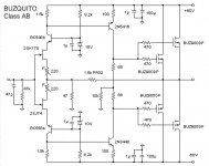
Build a BUZQUITO class AB. It may fit your expectations.
If your ears cannot cope with class AB, transform it for class A operation.
The info is available here : 2A & DIY
I have attached the schematic.
As a last word, please stop publicly talking about a PSA 150 S (Pure Sound Amplifier - Stereo). If you want to complete your project, call it a modernized SMD stereo Leach amp, and everybody will feel better. Remember that as the Leach amp is a class AB design, if you want to have a chance to gain the audiophile market, you need to show that you master ground pollution, rail induction and inductive distorsion.
So in a nutshell, if you are smart you should be able to a) convert the BUZQUITO into a switchable class AB / class A amplifier and b) remove the two ground pollution sources in the BUZQUITO.
The class AB / class A switch can be made using two transistors as pseudo-zeners, instead of the 68 ohm + 68 ohm resistors.
The cascode ground reference is a ground pollution source. How would you remove such pollution ? Using an opamp for generating a virtual ground ?
The 10K resistor as VAS load is another ground pollution source. You may remove the 10K resistor but as consequence the low frequency open loop gain will go up. That's not a big issue. You may be happy like this. If you still want to reduce the open loop gain at low frequencies you may introduce local feedback using series RC networks, between the output and the VAS bases. Say 1 Meg and 15nF. Oops, this means two more capacitors. And at startup, the power supply rail transient will cause a huge current in the VAS. So you need a VAS current limiter.
Basing on this, you may introduce fast & linear BJTs at the output instead of lateral MOSFETs. Using BJTs you may opt for a non-switching class AB like Kawanabe (working for Pioneer) filed in feb 1979 under number US 4.254.379. And check if it is not ruining the THD performance.
Steph
There is something you will need to explain to me.
Did you know about the Leach amp before drawing the PSA 150 S schematic ?
If you say no, this means that after 4 months on DIYaudio you don't know the existence of the Leach amp dating back from 1977 ? That's simply not possible.
If you say yes, this means that in a normal world, you already built a Leach amp, and like some people, you found the sound quite dull compared to some particular audiophile amps designed for subjective results like "Zen" or "single-ended triode".
Actually if you own speakers able to deliver 35 Hz to 17 kHz in a corridor of 2dB, you should not feel that the Leach amp is lacking expressivity.
Like millions of people, you may own speakers unable to deliver the full audio bandwith, especially in the deep bass range. So, in order to "fill" the blanks, you are in search of a power amplifier having some magic, like generating subharmonics when stimulated by a heavy pulsating signal enveloppe. Single-ended vacuum tube are perfect at this. Now you understand why there can be a good match with single-ended vacuum tube amps coupled to high-sensitivity speakers, mostly lacking energy in the deep bass range.
Or, maybe you have golden ears. You maybe can perceive granularity in sound at extreme low levels, and the fact that the Leach amp is not a class A amp, with big rectified currents flowing here and there, aggraved by a few ground pollution sources (wires quality becomes paramount), effectively corrupts the whole stuff by ground pollution, mutual inductance and radiation. In a nutshell, if you have not managed the ground pollution sources, and if you have not wired the ground output devices using magnetic field cancellation rules (you knew about this ?) with carefully matched loops, as determined by Douglas Self (rail induction) and Ed Cherry (inductive distorsion), then my friend, the only solution for you is class A. Or class D maybe.
Now you realize that the Leach amp has a capacitor at the input, and a capacitor in the feedback path. Like millions of people, you think that the capacitors may be the cause of your deception. Like me you know that capacitor sound is at the origin of a huge and passionate debate.
Let me help put you on the right track. Do a cheap experiment.
Build a BUZQUITO class AB. It may fit your expectations.
If your ears cannot cope with class AB, transform it for class A operation.
The info is available here : 2A & DIY
I have attached the schematic.
As a last word, please stop publicly talking about a PSA 150 S (Pure Sound Amplifier - Stereo). If you want to complete your project, call it a modernized SMD stereo Leach amp, and everybody will feel better. Remember that as the Leach amp is a class AB design, if you want to have a chance to gain the audiophile market, you need to show that you master ground pollution, rail induction and inductive distorsion.
So in a nutshell, if you are smart you should be able to a) convert the BUZQUITO into a switchable class AB / class A amplifier and b) remove the two ground pollution sources in the BUZQUITO.
The class AB / class A switch can be made using two transistors as pseudo-zeners, instead of the 68 ohm + 68 ohm resistors.
The cascode ground reference is a ground pollution source. How would you remove such pollution ? Using an opamp for generating a virtual ground ?
The 10K resistor as VAS load is another ground pollution source. You may remove the 10K resistor but as consequence the low frequency open loop gain will go up. That's not a big issue. You may be happy like this. If you still want to reduce the open loop gain at low frequencies you may introduce local feedback using series RC networks, between the output and the VAS bases. Say 1 Meg and 15nF. Oops, this means two more capacitors. And at startup, the power supply rail transient will cause a huge current in the VAS. So you need a VAS current limiter.
Basing on this, you may introduce fast & linear BJTs at the output instead of lateral MOSFETs. Using BJTs you may opt for a non-switching class AB like Kawanabe (working for Pioneer) filed in feb 1979 under number US 4.254.379. And check if it is not ruining the THD performance.
Steph
Attachments
Last edited:
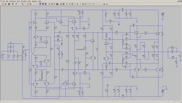
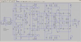
Quite a circuit this one. It seems mostly conventional, but the drawing is a little too arty in places and that confuses me at times. ")
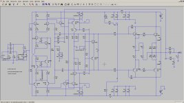
Here is my effort in LTspice so far. Mostly done, but still have to add component values and check for errors.
Here is my effort in LTspice so far. Mostly done, but still have to add component values and check for errors.
Attachments
Last edited:
Fantastic job. As a starting point, you may use the same semiconductors and directives as the original Leach amp LTspiceIV simulation file developed by Valerio Maglietta, available here Leach Amp Plans - Part 1Quite a circuit this one. It's mostly conventional, but the drawing is a little too arty in places and that confuses me at times. Here is my effort in LTspice so far. Mostly done, but still have to add component values and check for errors.
See attached file.
Attachments
Last edited:
hello,
ingenieus, thank you very much for the help..when the components will come (in aprox one and a half week) i will post the results (pictures and maybe some results), untill then, i am learning from you all and studying new and old designs;
mr steph, i know about the leach amp (i did't build it, and i didn't know how it sounds--to do that i need to listen to one "live" to tell you how it sounds), that's why i have said from the begining, that the PSA amp has been created with some concepts used in allot of amps, i only knew that it was inspired from Motorola amp, Leach amp and McIntosh Audio and the others..
Now i am studying the Lt spice program, because i want to try other input concepts for this amp..
Regards
sergiu
Hello sergiu2009,
come on, it is getting mad. There is no logic in what you say. So you still need to listen to a "live" Leach amp. Do you honestly think that randomly adding bells and whistles to a Leach amp will make it better sounding ?
Try to see clear in yourself. Your only preocupation and motivation is how to get rid off the two capacitors in the signal path, without degrading the Leach amp. This is indeed a decent starting point. You must be the zillionth person dealing with this.
Take one night thinking about this, and reply to me tomorrow morning.
I'll appreciate that you take into consideration the following considerations :
- will you use a DC-coupled input (is the source guaranteed DC-exempt ?)
- is the source a volume potentiometer with a highly variable internal DC resistance like 0 ohm to 25k ohm ?
- according to you, what is the max tolerable DC polarization current ?
- do you reject a solution consisting on a opamp acting as DC-servo (one or two capacitors) ?
- are you considering replacing the four input transistors by four FETs (possibly cascoded) ?
- are you considering replacing the four input transistors by one FET opamp (Kuroda arrangement) ?
After you succeed in one of those transformations, are you going to try modding the Leach amp in a well structured way like progressively applying to the Leach amp the "blameless" receipes and criterions ? Again, this is indeed a decent starting point. Again, you must be the zillionth person dealing with this.
- read Douglas Self book "Audio Power Amplifier Design Handbook, 5th Ed"
- start cascoding the input transistors (especially if they are FETs)
- load them by a current mirror (be very careful for the VAS bias stability, urgently need to read the solution that got proposed by Linsley Hood)
- add a Beta enhancer
- cascode the VAS
- try the so-called folded VAS cascode (or the Lender arrangement ?)
- make sure the bias voltage regulator (pseudo zener) is stable, and optimally HF-decoupled
- limit the gain using loading resistors and degeneration resistors
- try a CFP output instead of a Darlington (and maybe allow some gain in the CFP)
- persuade yourself that Douglas Self forgot the ground pollution syndrom
- as a consequence, do not consider the ground like a trashcan or a sewer
- regarding the PCB design, remember the big rectified currents flowing into the output devices (high harmonic content), minimize the magnetic field (try cancelling the two fields), and reduce the mutual coupling inductive pickup according to Ed Cherry rules
Make sure the over-current protection is not impacting the performance.
Make sure, if you are using a relay against DC-out, that the contact points remain perfect over time.
Ask yourself if you want your amp to be class AB, high-bias class AB, or class A. Finally, like previously said, ask yourself if you want your amp to be class AB with some refinements like "non-switching" class AB or a "soft non-switching" class AB. Start reading the Kawanabe patent (working for Pioneer) filed in feb 1979 under number US 4.254.379. And check if it is not ruining the THD performance.
Now you face what modding an amp really is !
Good luck !
Last edited:
Quite a circuit this one. It seems mostly conventional, but the drawing is a little too arty in places and that confuses me at times.
Here is my effort in LTspice so far. Mostly done, but still have to add component values and check for errors.
We look forward to complete simulation PSA150S schematic , and try to improve in our vision , where appropriate values of some components in order to increase performance and reducing distortions , using the same schematic , no use Kawanabe patent or other audio tricks .
Thanks for the effort and invite you to join us in construction this project audio amplifier.
Last edited:
Why don't you first build the A Class AB Amp for diyAudio ?
http://www.diyaudio.com/forums/solid-state/192431-class-ab-amp-diyaudio-17.html
Post #165 : in the attachement it reads "---- LTP ---- Comprised of Q1 and Q2 , C1 - C4 , R1 - R6 , and D1 - D2. This stage is the "first in line" , it sees both your music input signal and a attenuated version of the final amplifed signal. It is called a "long tailed pair" or "differential input pair", "LTP" for short. You can choose many devices for Q1 and Q2 ,as long as they are E-B-C in lead designation and have low noise and high gain (200Hfe+ - 3-500 preferred)... 40-65V NPN To-92 BJT. FET's can be used with this amp and will be offered as a future modification."
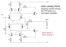
If you feel happy about the specs and the sound, try deriving a symmetric version of it. You'll get trouble stabilizing the VAS bias current (because of the current mirrors LTP collector loads) but as already explained above, Linsley Hood made a proposition that you may try. Or you can use resistors as LTP collectors loads.
http://www.diyaudio.com/forums/solid-state/192431-class-ab-amp-diyaudio-17.html
Post #165 : in the attachement it reads "---- LTP ---- Comprised of Q1 and Q2 , C1 - C4 , R1 - R6 , and D1 - D2. This stage is the "first in line" , it sees both your music input signal and a attenuated version of the final amplifed signal. It is called a "long tailed pair" or "differential input pair", "LTP" for short. You can choose many devices for Q1 and Q2 ,as long as they are E-B-C in lead designation and have low noise and high gain (200Hfe+ - 3-500 preferred)... 40-65V NPN To-92 BJT. FET's can be used with this amp and will be offered as a future modification."
If you feel happy about the specs and the sound, try deriving a symmetric version of it. You'll get trouble stabilizing the VAS bias current (because of the current mirrors LTP collector loads) but as already explained above, Linsley Hood made a proposition that you may try. Or you can use resistors as LTP collectors loads.
Attachments
Last edited:
We look forward to complete simulation PSA150S schematic , and try to improve in our vision , where appropriate values of some components in order to increase performance and reducing distortions , using the same schematic , no use Kawanabe patent or other audio tricks .
Thanks for the effort and invite you to join us in construction this project audio amplifier.
Uhm, have you got any values for R136, R138, R139, R141, R143, R148, R144, R145, R146, R147 yet? I can't continue without these. Even approximate values will help.
Uhm, have you got any values for R136, R138, R139, R141, R143, R148, R144, R145, R146, R147 yet? I can't continue without these. Even approximate values will help.
Thank you for your interest.
SOA protection component values were computed for a supply voltage + / - 45 Vdc with transistors SOA 0.8A / 100V ( 2Sc5200 + 2SA1943) and is not sure for type MJL and supply voltage + / -55 Vdc , gives me advice after simulation for best value
R136 is 47Kohms
R137 is 10Kohms
R138 is 100ohms
R143 is 100ohms
R144//R145 is total value 2K2 / 1W
On the negative alternation ( mirror ) are the same values........you know .
Please sorry for my bad English
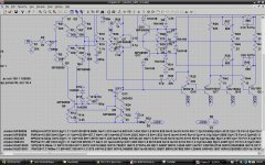
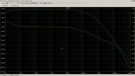
Here are the results.
Output power: 50W into 8 ohm at 1kHZ with 0.8% THD
Tweaking the bias pot does little to change this.
Clipping occurs at about +32V.
The LTspice file is attached. The models used are attached as well. Remove .txt extensions to use.
Add a SPICE include directive to schematic, i.e.
.include models.inc
Output power: 50W into 8 ohm at 1kHZ with 0.8% THD
Tweaking the bias pot does little to change this.
Clipping occurs at about +32V.
The LTspice file is attached. The models used are attached as well. Remove .txt extensions to use.
Add a SPICE include directive to schematic, i.e.
.include models.inc
Attachments
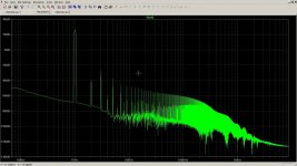
Without SOA circuit (as below), THD improves to 0,24% at 60W.
FFT reveals quite a lot distortion.
Phase margin is not looking good even with closed loop.
With those jumpers in place, only the negative half of the waveform appears.
Back to the drawing board,I would say. LTspice and the schematic in my previous post will help with that.
FFT reveals quite a lot distortion.
Phase margin is not looking good even with closed loop.
With those jumpers in place, only the negative half of the waveform appears.
Back to the drawing board,I would say. LTspice and the schematic in my previous post will help with that.
Attachments
Last edited:
For a correct simulation, please make the following changes: eliminate C7 and C8; R9 and R10 resistors are 1Kohm, R50, R51, R42, R49 = 5.6 R, R15 = 120k, please eliminate from the schematic the circuit JP1, JP2 (because we dont need them),and connect correctly R51 between the C22, C23 and C24, C25 capacitors... DZ3 and DZ4 are rated at 3.9 volts.
- Status
- This old topic is closed. If you want to reopen this topic, contact a moderator using the "Report Post" button.
- Home
- Amplifiers
- Solid State
- PSA 150 S (pure sound amplifier)---help needed