Hi all,
I have to work some more (on simpler schematics and then with the PSA..) with the lt spice program for the simulation of the reactive load on the output...thank you very much ingenieus for the help with the exemplification of the problem that Nico mentioned.
When this problem is solved i will post what i had in mind with this schematic..
Regards
Sergiu
Last edited:
hello,
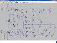
this is what i had in mind for the output of this amp (psa 150s) from the begining...it is a rough schematic, without values for the components (i have taken a bit from here, and a bit from there to have a begining to start with); i want to combine a non switching design with a bryston topology (i have seen it before on our forum in the"crosser amp" with very good results );
here is the link:
Imageshack - psa150snew.jpg
what do you think? could we apply these wonderfull topologies to the psa 150?
does anybody have some ecuation/formulas for the component values from the schematic that i was thinking about?
regards
sergiu
PS: i'm still thinking for the input (for the elimination of the input caps)..
Last edited:
Use the Insert Image button to make the Imageshack picture part of the post.
Like this:
Like this:
An externally hosted image should be here but it was not working when we last tested it.
need help with the simulation
hello,
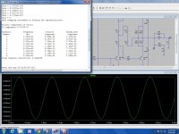
i have put a sziklay compound pair on the both inputs; i have atached a picture of what i had obtained in LtSpice and the asc.txt file wich shows the way that it have connected the trasistors and the values.....
ingenieus could you help me simulate this topology on the input please?
i want to see if i have lowered the output power with the 650 ohm value for the resistors, because initial i had in mind 680 ohm and, what good did i do to the schematic..
i didn't see if the components have the right values or if they are well arranged (i'm hoping that ingenieus has the correct schematic), i only wanted to show what i had in mind..
what are the advantages with this kind of topology on the input?
regards
sergiu
hello,
i have put a sziklay compound pair on the both inputs; i have atached a picture of what i had obtained in LtSpice and the asc.txt file wich shows the way that it have connected the trasistors and the values.....
ingenieus could you help me simulate this topology on the input please?
i want to see if i have lowered the output power with the 650 ohm value for the resistors, because initial i had in mind 680 ohm and, what good did i do to the schematic..
i didn't see if the components have the right values or if they are well arranged (i'm hoping that ingenieus has the correct schematic), i only wanted to show what i had in mind..
what are the advantages with this kind of topology on the input?
regards
sergiu
Attachments
I think there is something wrong in the VAS, especially the Q10 emitter circuit and the Q13 emitter circuit.hello, i have put a sziklay compound pair on the both inputs; i have atached a picture of what i had obtained in LtSpice and the asc.txt file wich shows the way that it have connected the trasistors and the values... I didn't see if the components have the right values or if they are well arranged (i'm hoping that ingenieus has the correct schematic), i only wanted to show what i had in mind.. What are the advantages with this kind of topology on the input? regards sergiu
- Status
- This old topic is closed. If you want to reopen this topic, contact a moderator using the "Report Post" button.
- Home
- Amplifiers
- Solid State
- PSA 150 S (pure sound amplifier)---help needed