Interesting thought!
I'll try to hook the probe to different value of resistors and see what i get.
At the output i have 4.7Kohm resistor on each side.
Actually i don't see ...... 50Hz at the output with the scope...i see a various harmonic....and the noise should be around 1.5mV pk-pk.....
When i hooked the preamp up just yesterday to my speaker i heard a 50Hz....low...noise on the woofer (so there must be a little bit ...it's just not easy to see it with a 5mv/div sensibility) ....but what bugs me the most is the noise on the tweeter.
I do agree with you that there must be some i don't know ..oscillation...very low value...but unfortunately acting on the gate stopper resistor doesn't do anything in this case.
Thanks for your info.
So i shouldn't have a oscillation by touching the mosfet...so there is a problem.
Another thing...is that the circuit...as i said seems to be very sensitive to the temperature variation...it's like if there wouldn't be thermal stability.
I'm running the mosfets without heatsink so i guess that this might be the reason since the IRF9610 gets hot (about 80 C).
So you have any heatsink on your board?
At this point...my only two cents are on the wrong layout that causes parasitics oscillations.
Monday i'll burn the new board and see what happens with that and keep you posted.
As soon as i'm done with the board i will try to build this little op amp front end for the scope.
Hi Stefanoo,
I don't have any specific setup procedure and am reluctant to give any specific advice as i am no expert at all (certainly not with oscillation). Better follow analog sa there.
I see that you've followed Analog's advice and that it gave you some new insight, nice!
The reason for my asking had to do with what analog sa is saying. As other's have said I believe your scope is ok, you are seeing stray fields with that signal.
Even with no power on the circuit it acts as an antenna. The way you wire your test setup, makes that this effect will be less or worse. Due to the fact that the wiring will be part of the antenna. Your scope is a very sensitive measurement tool and will measure the signal from that antenna.
From the pictures you posted i see that you've made the ground connection directly through the probes alligator clip. The signal however seems to go through an extra piece of wire and is attached to the probe with a clip. There is another connection there as well, the multimeter? I would try to measure directly across the resistor between the output and ground, no wire's in between or attached. Wire's in between will only make the antenna effect stronger.
regards
Joris
in fact for my last measurements, as i said, i have changed set up and i had soldered in the BNC cable to the output of the pre....in rder to not have the ground clip with the extra cable to pick up other noise.
I'm seeing how difficult it is to make a reliable measurement for very low value signal...but i think it is intriguing.
I' ll keep you guys posted as the new layout is up.
Best,
Stefano.
P.S. rtirion thank for your suggestion......i' ll try this out on the old layout and on the new as well.
I'm seeing how difficult it is to make a reliable measurement for very low value signal...but i think it is intriguing.
I' ll keep you guys posted as the new layout is up.
Best,
Stefano.
P.S. rtirion thank for your suggestion......i' ll try this out on the old layout and on the new as well.
just one thing...that hasn't to do with with the pre....but has to do, instead, with the X2.2,3 and therefore UGS module.
Since they use the 2SK387BL and 2SJ107BL...and since these are old devices they are no longer available, i was wondering if there are new devices that can be used...or if anybody knows where it is possible to get some.
Since they use the 2SK387BL and 2SJ107BL...and since these are old devices they are no longer available, i was wondering if there are new devices that can be used...or if anybody knows where it is possible to get some.
Stefanoo said:just one thing...that hasn't to do with with the pre....but has to do, instead, with the X2.2,3 and therefore UGS module.
Since they use the 2SK387BL and 2SJ107BL...and since these are old devices they are no longer available, i was wondering if there are new devices that can be used...or if anybody knows where it is possible to get some.
hardly those types . look at attachment
besides - if you have serv manual for some UGS , you will still need help for implementing it in anything practical .
Attachments


Stefanoo,
You get more sensitivity in your scope by cascading the two channels. see in your owners manual.
The use of one shielded cable (RG-58 RF coaxial is ok and fits OK in both BNC and RCA plugs) in oscilloscope is OK for audio, specially for noise analysis. Normal scope probes have a very poor shielding.
For audio, always use the "20 MHz bandwidth limiter" in the scope. you give a more clear and "focused" trace.
And, the damped oscillation you see in your scope is not originated in your preamp. it is only a repetitive noise generated by some SMPS or "electronic" lamps.
If your circuit oscillates, you see a clean and continuous HF signal instead of signal that you showed.
Try to use your scope in differential mode (add channels and invert channel 2)... and you have a balanced scope...for free.
Hope this help,
Marcos
m2003br said:Stefanoo,
You get more sensitivity in your scope by cascading the two channels. see in your owners manual.
The use of one shielded cable (RG-58 RF coaxial is ok and fits OK in both BNC and RCA plugs) in oscilloscope is OK for audio, specially for noise analysis. Normal scope probes have a very poor shielding.
For audio, always use the "20 MHz bandwidth limiter" in the scope. you give a more clear and "focused" trace.
And, the damped oscillation you see in your scope is not originated in your preamp. it is only a repetitive noise generated by some SMPS or "electronic" lamps.
If your circuit oscillates, you see a clean and continuous HF signal instead of signal that you showed.
Try to use your scope in differential mode (add channels and invert channel 2)... and you have a balanced scope...for free.
Hope this help,
Marcos
interesting thoughts.
I will like to find a better shielded cable for the probe .... i'll look around and see if there is any information on internet.
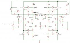
The new layout is up.
Layout is simple and allows testing since all the tracks are very spaced one within another.
I hooked it up after having verified that no autoscillation was going on.
With my big disappointment the sound was displaying some problems.
So i unplugged in and take it back on the test bench.
by checking the output of a square wave (with a sine i didn't have any problems), the output was hardly distorted.
So i tried to find the problem and after have changed the capacitor across C-E on the CCS transistor from 460pF to 680pF (suggested value on the SM) the output is now ok.
Nevertheless i can still see a little 50Hz on the output.
tomorrow i'll check it out better and i will try to connect it to the stareo system and see what's new.
now after have changed that capacitor if i touch the mosfets i don't have any instability....interesting!!!
Tomorrow i'll take some pics and post them here.
That's all folks for now...
I still have the very same noise even with the other design.
But what is changed now...is that i cased the preamplifier and the noise was lowered a lot.
So i started thinking that the problem could be caused by a bad grounding since it changes a lot with the grounding of the circuit.
I am going nut trying to understand this subject and read many informations on the forum and tried already different configuration without success.
I would like to see if anybody here can help me.
I am currently running just one channel and so just one trafo inside the case.
The power supply is on the same board for practical reasons.
I have a star ground on the center of the preamplifier board where all the ground signals are merging to and i have a star ground on the PS unit right by the second capacitor.
I have tried to put a bridge as a ground loop breaker on AC side connected to the chassie and the DC side as a center star....but nothing the noise is still there.
Any suggestion is welcome.
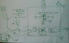
I have drawn a ground schematic to show you guys the arrangement of the ground.
I am currently running just one channel on single ended and therefore i short the IN- to ground.
I have fixed resistor from OUT- to ground (and OUT+ to ground) of 2.2Kohm and i take the output at across OUT+ and GROUND.
I tried to connect the bridge ground loop breaker to the center star B.
I tried to connect the ground oh input - output togeter and take it as a center star and run a wire to the center B...but none of this arrangement had solutioned the problem.
I don't have the earth connected to the chassie right now, but i don't has to do with the noise at the output.
Can anybody give me some advice please?
Any effort is very appreciated.
Thanks for the attention.
Attachments
just a thought...
i haven't tried the above solution yer but i don't think has to do with the noise since it does that when input are shorted (in+,in- shorted to ground) and therefore SE or nor i think the circuit should be silent in that condition.
Nevertheless i am curious to try to short the out- to see how it affects the sound of the preamplifier.
If any idea on the ground wiring comes up...i' ll be glad to try that out and see if it will solution the problem.
Zen Mod said:if you are using SE output , you must ground - out .
check that - I'm sure that you'll find difference
Why is this? Seems odd to me to be having (-) output currents
being returned thru ground rather than just allow it to float.
It seems like the SE arrangement is suboptimal and tying
output to ground won't help with a whole lot.
Zen Mod said:if you are using SE output , you must ground - out .
The reason for this is simple - the SuSy circuit doesn't bother
to correct common mode distortion and noise, so if you look
at just one of the balanced outputs, the distortion and noise
looks pretty much like the open loop performance of the circuit.
If you short the unused output, then the circuit no longer sees
the distortion and noise of the other output as common mode,
and the feedback reduces it.
- Status
- This old topic is closed. If you want to reopen this topic, contact a moderator using the "Report Post" button.
- Home
- Amplifiers
- Pass Labs
- preamplifier Pass X2.0/1