Nelson Pass said:
The reason for this is simple - the SuSy circuit doesn't bother
to correct common mode distortion and noise, so if you look
at just one of the balanced outputs, the distortion and noise
looks pretty much like the open loop performance of the circuit.
If you short the unused output, then the circuit no longer sees
the distortion and noise of the other output as common mode,
and the feedback reduces it.
post No. 100


yes i can quote.
i tried to short the - output and i was able to hear an improvement on the overall sound quality.
But...as Wayne said ....didn't help much about noise.
Can anybody give me good tips on how to fix this problem with fuzzy noise on the tweeter and a little hum noise on the woofer?
I personally had two ideas:
-one was about the pnp and npn transistors used....since i am not using a 100hfe transistor....i thought that this may have changed something on the stability of the circuit.
i started to play with the capacitors across the CE junction of these transistors...and i don't understand why if i put let's say a different value from the suggested 680pF i get 5.85V (instead of the 15V) on the input coupling capacitor and 11.85V (instead of the 29V) on the other...on one side and 0V on both coupling capacitors of the other side and i get nothing at the output when input is fed with a test signal.
But what i have at the output with such a capacitor value is a flat trace ....no fuzzy no hum....but unfortunately not working...and that was addressing me to think that the problem could be in that art of the circuit and therefore on the type of transistor used.
but i guess that accordingly on what Mr. Pass said on other posts those transistors shouldn't be ruling at all and that a whatever low noise general purpose transistor was ok....than i started to abandon that idea...
I have just noticed that by changing the type of transistor this affects the sound.
I tried different transistors and got a slight but significant difference.
Second idea...when i started playing around with the ground inside the case and got a significant variation on the tweeter/woofer noise depending upon the arrangement on the ground i started to consider that that could be the cause of the problem.
Since i am not doing something right with the ground and i am sure i am missing something....can anybody please help me out with this?
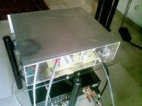
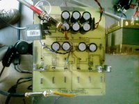
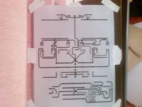
Finally the layout...
as you can see i have the power supply board on the same board...but i have two separate center star...one on the pre side that shares the ground with the 4 extra filtering capacitors and one on the psu board that is placed on the middle of the filter capacitors.
the layout was made purposly wide to make modification and jobs around easier....the final layout will be more dense and smaller though....
Attachments
Nelson Pass said:
The reason for this is simple - the SuSy circuit doesn't bother
to correct common mode distortion and noise, so if you look
at just one of the balanced outputs, the distortion and noise
looks pretty much like the open loop performance of the circuit.
If you short the unused output, then the circuit no longer sees
the distortion and noise of the other output as common mode,
and the feedback reduces it.
Hmm Interesting. Mr Pass, how do you implement this on your commercial amps, would you recommend adding al little switch on the back of the pre witch would connect the neg channel to the ground in case the pre is used SE?
cheers,
c
hi manu,
no i don't notice any difference by moving the transformer.
I tried already to wire the output of the power supply to the main star ground on the center of the board but nothing.
Is there anybody that have built the veteran board and success?
If so, would it be possible to know the ground arrangement inside?
thanks a lot.
P.S i am not using a thermistor i don't know ....i don't have it...but i am using a bridge in place of it.
I made further tests and hope these can help to detect the problem.
1- i have found out that the noise on the tweeter starts few seconds after the circuit is powered up (something like 6-7 seconds)
=> i tried to see if any of the resistors or some diode was getting too hot (all the resistors are 0.25W rated).
The only thing was getting warm, beside the mosfets, were the zeners string on the power supply.
So i did rise up the current limiter resistor, lowering therefore, the bias current for the diodes.
After this modification, noise on the tweeter was still there but starting with delay (something like 15seconds).
I would like to outline the fact that If i would play music within this 15 transit seconds, the circuit would normally play.
I try to track the voltage across the output capacitors to see if the noise would appear at a certain voltage value.
But the output capacitor's voltage drop settles at 31V and then after few seconds noise starts.
2- i tried to change the filter caps to see if one of the capacitors was defective.
I was currently using 8 X 2200uF rated at 100V.
I swap them with a much lower capacitance (6 X 680uF capacitors) but at higher voltage rate (400V).
The result was that the noise was till there, but the sound was much more opened and cliear and better in general.
Then i tried to put a 0.1uF cap across the zener's pile and 47nF right across each rectifier diode.
The result was an overall improvement on the sound quality but nothing for the noise on the tweeter.
3- i tried to put in backwards all the bjts just to be a camicaze....ehehe....(i was doubtful in regard to the footprint).
With my big surprise, the circuit was still correctly working and the noise' situation was still exactly the same!
Then i started to reason on the rule of those transistors and got to the conclusion (certainly wrong!) that these transistors are just controlling that the current on the devices won't go over a certain amount.
So i tried to take them off the circuit and the result was that the circuit was noiseless for something like 20-25 seconds and then began to smoke.
4- i tried to evaluate if the problem was due to the fact that the transformer was on the proximity of the circuit and so i pull it off the metal case.
=> the result was that the slight noise on the woofer was completely disappeared (great!) BUT the noise on the tweeter still there.
The transformer, when on, buzzes a little bit and i don't know if this buzzing can go through the power supply through the cable and from there directly coupled to the circuit......this is just an idea.
and that is it.
This is how far i have gotten so far.
Hope somebody can help me to detect the problem which is driving me crazy.
Best.
- Status
- This old topic is closed. If you want to reopen this topic, contact a moderator using the "Report Post" button.
- Home
- Amplifiers
- Pass Labs
- preamplifier Pass X2.0/1