spzzzzkt said:Tantalums????
Black gate NP's are the minimum quality I would be using for coupling caps in the P1.7. I tried ERO MKT's initally and they were distinctly worse than the BG's.
I dread to think how tants would sound.

ehehehe i knew somebody would have said something about tantalium.....but that was the only thing i had available.
Sorry but what type of cap does NP use on his project? BG?
Which model.
Would you kindly point me a link on the capacitor that you would suggest me use?
As i said NP suggest me the Zen Caps...have you ever tried those?
Zen Mod said:
Stefano, with respect - but seems to me that you are biting too much for your knowledge level ;
it's completelly fine asking and wishing to know more , but - most important thing is knowing one gadget before going to another ..... only then you can understand difference between them .
try to remove flaws in your present preamp, then move to another one , if you stiil need that .......
post schematic here ( that's your homework, not anyone else's - to chase it) and then we can discuss it - where you (maybe) miss something and what you can improve.
point is - that preamp is still one of most cherrished in DIY world, not without reasons
sorry you are right....i haven't posted the schematic.
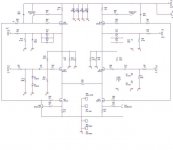
This is the NP SM schematic.
The gain resistor R51 is set up to 240 (is it too low? might it cause some hiss?)
Are the R48-R63 the feedback resistors that grey was talking about?
Attachments
Stefanoo said:
Would you kindly point me a link on the capacitor that you would suggest me use?
As i said NP suggest me the Zen Caps...have you ever tried those?
I am using the Zen capacitors bypassed with Harmony caps in my P1.7 clone. The sound was noticeably improved compared to the Panasonic 10uF metallized polyester caps Grey mentioned earlier and they are reasonably priced. I haven't tried other capacitors or many other pre-amps, so my experience is quite limited.
It is difficult to tell if North Creek is still selling components to hobbyists. The information on their web site is ambiguous.
Jeremy
I keep a few of those Panasonic 10uF caps around for quick-n'-dirty work, but I no longer use them in anything serious. The main thing going for them is that they are economical by film cap standards.
Trying to evaluate anything with tantalum caps in it is bound to lead to frustration and/or inaccurate conclusions. I'm not exactly sold on the idea of using electrolytics--regardless of manufacturer--in signal coupling applications under any but the most dire of circumstances.
Stefanoo,
This is probably one of those things that you'll have to solve on your end. It's quite possible that your circuit is oscillating. Your expectation that oscillation will grow and grow in the sense of feedback that you might hear through the PA system at a concert is not entirely accurate. The first thing to realize is that if the circuit is oscillating at, say, 1MHz, it could actually be oscillating at full power and you couldn't hear it no matter how hard you listened. Second, oscillation isn't necessarily an all-or-nothing proposition. If a circuit is oscillating, it's due to a complex relation between impedances and the period of the oscillation (hence the rise time of the signal) may be so short/fast that the signal doesn't have time to reach full output before it's time to turn around and head south again.
If your oscilloscope is in need of repair, you might want to consider getting it fixed, or perhaps buy a new one. I use a Tektronix 7300 scope which has something like a 100MHz bandwidth if you're using the right plug-ins. You'd be surprised how high the frequency of an oscillation can be. No, you don't necessarily have to buy a 7000 series to look at things (although Ebay and patience can work wonders), but a decent scope is one of the first things I'd buy if I were starting from scratch. Hooking a piece of equipment that may be oscillating to your speakers could easily cost you a new set of tweeters--it most certainly isn't the best way to check for problems.
If your circuit is actually oscillating, even at frequencies far above human hearing, it can have an effect on the sound quality.
Grey
There was substantial body of opinion on veteran's P1.7 thread that the BG N's were better sounding than cheaper polyprops ie solens/axons. Veteran's boards were (unfortunately imo) designed with just enough room to fit 10uF Wima/ERO MKP's which I've found difficult to source. I think stenafoo has room on his boards for bigger caps?
I've gone with the BG's N which sound pretty fine but are clearly not the last word in refinement. That said the BG N's should give a good idea of what the P1.7 is capable of before spending $100's on coupling caps.
I've gone with the BG's N which sound pretty fine but are clearly not the last word in refinement. That said the BG N's should give a good idea of what the P1.7 is capable of before spending $100's on coupling caps.
B&W's and Electrocompaniet
Stefano,
Just by the way, I think there is a certain synergy between the smaller B&W 800 series speakers and Electrocompanient ECI-4 which makes the combination very pleasant. Please note that I don't have access to the high end shops here in Austrlia, and I have never heard any commercial (i.e. REAL) Nelson Pass amplifiers nor anybody else's NP clones either. My point is that Electrocompaniet's amplifiers just go nicely with B&W for my taste.
But looking at this thread there are many other good reasons you are not having luck with your P1.7 - especially crumby caps and other technical problems. You really need to work them out before pursuing another project to get a reasonable "bang for you buck" and the effort you have put in, and to give the Nelson Pass circuits a "fair" test at the DIY level. I am still living with a half-baked Threshold NS10 clone I threw together one weekend and thoroughly enjoying it. I would be surprised if a properly built Aleph P1.7 was not a very, very strong performer.
Regards,
George.
Re: B&W's and Electrocompaniet
George,
you have caught the point and i do agree with you.
I feel like that there is a nice synergy but i had also listened to other combinations with higher level amplifiers and even if the result might not be as pleasant as in this configuration here, you can clearly hear the higher components quality.
BmW is a real monitor in the sense of: the better the parts drving the better the result.
Upon this last concept my opinion wasn't driven from the pleasure of a certain sound, but from the quality of the sound.
Anyways.....what i'm gonna do is change the capacitors and check for oscillations and see that everything is ok and then eveluate the project.
I'm sure i'll be very surprised.
GeorgeBoles said:Stefano,
Just by the way, I think there is a certain synergy between the smaller B&W 800 series speakers and Electrocompanient ECI-4 which makes the combination very pleasant. Please note that I don't have access to the high end shops here in Austrlia, and I have never heard any commercial (i.e. REAL) Nelson Pass amplifiers nor anybody else's NP clones either. My point is that Electrocompaniet's amplifiers just go nicely with B&W for my taste.
But looking at this thread there are many other good reasons you are not having luck with your P1.7 - especially crumby caps and other technical problems. You really need to work them out before pursuing another project to get a reasonable "bang for you buck" and the effort you have put in, and to give the Nelson Pass circuits a "fair" test at the DIY level. I am still living with a half-baked Threshold NS10 clone I threw together one weekend and thoroughly enjoying it. I would be surprised if a properly built Aleph P1.7 was not a very, very strong performer.
Regards,
George.
George,
you have caught the point and i do agree with you.
I feel like that there is a nice synergy but i had also listened to other combinations with higher level amplifiers and even if the result might not be as pleasant as in this configuration here, you can clearly hear the higher components quality.
BmW is a real monitor in the sense of: the better the parts drving the better the result.
Upon this last concept my opinion wasn't driven from the pleasure of a certain sound, but from the quality of the sound.
Anyways.....what i'm gonna do is change the capacitors and check for oscillations and see that everything is ok and then eveluate the project.
I'm sure i'll be very surprised.
spzzzzkt said:There was substantial body of opinion on veteran's P1.7 thread that the BG N's were better sounding than cheaper polyprops ie solens/axons. Veteran's boards were (unfortunately imo) designed with just enough room to fit 10uF Wima/ERO MKP's which I've found difficult to source. I think stenafoo has room on his boards for bigger caps?
I've gone with the BG's N which sound pretty fine but are clearly not the last word in refinement. That said the BG N's should give a good idea of what the P1.7 is capable of before spending $100's on coupling caps.
Yes my board is designed for bigger auricaps.
I was thinking of those caps since i read certain comments on them on the net.
The point is that....by making 4 calculations...the price for this preamp....is $140 for and ELMA 4 deks switch $120 for coupling caps (zen caps...if i would use the auricaps the price would be the double) and i would say another $100 in resistors supply caps mosfets power supply diodes; then another $150 for 2 nice plitron transformers.
ah...by the way if anybody is interested on using my board design with bigger space for capacitors....i will gladly share it.
I actually can manufacture some (i home make them) with througholes rivets and coating.
As far as i have seen around on the net...my board has the shortest paths and more elegant design........but i might be disillusioned
")
GRollins said:I keep a few of those Panasonic 10uF caps around for quick-n'-dirty work, but I no longer use them in anything serious. The main thing going for them is that they are economical by film cap standards.
Trying to evaluate anything with tantalum caps in it is bound to lead to frustration and/or inaccurate conclusions. I'm not exactly sold on the idea of using electrolytics--regardless of manufacturer--in signal coupling applications under any but the most dire of circumstances.
Stefanoo,
This is probably one of those things that you'll have to solve on your end. It's quite possible that your circuit is oscillating. Your expectation that oscillation will grow and grow in the sense of feedback that you might hear through the PA system at a concert is not entirely accurate. The first thing to realize is that if the circuit is oscillating at, say, 1MHz, it could actually be oscillating at full power and you couldn't hear it no matter how hard you listened. Second, oscillation isn't necessarily an all-or-nothing proposition. If a circuit is oscillating, it's due to a complex relation between impedances and the period of the oscillation (hence the rise time of the signal) may be so short/fast that the signal doesn't have time to reach full output before it's time to turn around and head south again.
If your oscilloscope is in need of repair, you might want to consider getting it fixed, or perhaps buy a new one. I use a Tektronix 7300 scope which has something like a 100MHz bandwidth if you're using the right plug-ins. You'd be surprised how high the frequency of an oscillation can be. No, you don't necessarily have to buy a 7000 series to look at things (although Ebay and patience can work wonders), but a decent scope is one of the first things I'd buy if I were starting from scratch. Hooking a piece of equipment that may be oscillating to your speakers could easily cost you a new set of tweeters--it most certainly isn't the best way to check for problems.
If your circuit is actually oscillating, even at frequencies far above human hearing, it can have an effect on the sound quality.
Grey
hi grey,
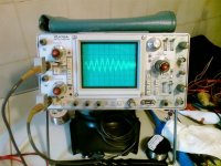
i have a tek 475A which is a 300MHz scope....unfortuantely has a power supply related problem and i checked and there should be a couple of caps that are not working.
I think it would be enough to replace them to fix it.
The problem is that in order to gain access to the main board with the power supply, i have to take all the boards of the scope aparts..and the scope is assembled with tooonnss of wires tackled inside, strips....yet, i have a detailed service manual and so one of this day i'm going to do it....but i'm a little scared not to be able to do it.
Yes it would be nice to get a new perfectly functional one instead of going through this hassle here.
With regard to the oscillation, i got a little scared.
The high frequency oscillation can cause the failure of output transistors and the speakers as you outlined.
Eventually if none of this happened and i had it connected to my amplifier and test speakers (not the B&W).....it might not be oscillating...or i was just fortuned.
Ether way i' m gonna check.
Actually i don't know if this could be an adding factor....but since i didn't have the Zetex 450/550 for the CCSs i used BC550C and BC372C which were the only one that i had available on my hand.
I have read that the zetex are not critical transistors and can be replaced with whatever general purpose pnp and npn with a similar hfe (100).
I also read on the forum of members who replaced these transistors with BC550 and 560C ....but these transistors have 300 of hfe...and i got a little confused.
So i plugged the above transistors in and since the circuit was working i stop worrying about the hfe.
But at this point i' m wondering...can this fact be affecting the stabilty of the circuit (i am going to order from mouser, together with other things the zetex transistors)
Yet i want to state one thing:
I tried to change the transistors on the CCS and since i had the zetex ZTX450 and BC332 and the BC550 i tried to switch these transistors registering a very different sound for each type of transistor used.
So it is NOT true that these transistors don't affect the sound...that is my experience that i enjoyed sharing with you guys.
Next time i'll connect something "homemade"
...upon your advice, grey......i'll be super careful with regard to high frequency oscillations.I'll make measurements with my scope for as much as i can do with it and post the results here.
Being goofy in the head, I called my main scope a 7300...it's actually a 7603. I knew it had a 3 in there somewhere. Actually, I've got two of them--the bench version and a rack -mount version of the same scope. Why? Because a year or two ago I took a week off from work with the intention of getting some electronics done and my scope went dead on the first day. Since then, I've made sure to have a backup at all times. Be damned if I'm going to go to all the trouble to take a week off and not get anything done.
Grey
Grey
GRollins said:The Pass X product schematics have never been released publicly.
Grey
Why am I not surprised that Grey is the one who injects some
thing worth reading back into the thread....
On this - there seems to me that most people do not understand
what patents are how they work.
While what Grey says is technically true, in spirit it is not true.
When writing a patent, the application MUST contian the BEST
embodiment known to the inventor. Otherwise the patent is
not valid, and if it could be shown to the contrary in a patent
dispute, the patent holder would lose his rights to the invention.
So although there is no full product schematic for the X products,
someone "skilled in the art" MUST be able to use the patent to
generate the thing being patented.
Ergo - if you are a good analog designer, you can easily make
an X amp merely using the info in the patent. But if you do this,
you are liable to litigation by the patent holder unless you gain
permission from that patent holder beforehand. This could be
a license arrangement, or cross-licensing, or (as usual in
Nelson's case...) "go knock yourself out".
That's how it works in civilized societies folks.... You must publish
the BEST known embodiment, and in return you gain the
protection to your idea in the Court system.
So. It should not be too surprising that there are poeple
generating amps that are in fact X amps (meaning they operate
subject to the principles of the X patent and enjoy an increased
20dB noise margin over a similar "balanced but not X" amp.
In those cases I hope those have the approval of the patent
holder.
Happy New Year everyone.
The best known implementation at the time of filing the patent application doesn't preclude further development--which is why Nelson no longer uses the MOSFET front end shown in the patent. The MOSFET front end works...obviously...but after a year or two, your curiosity begins to itch...what if I try this or perhaps this?
In the week since I finalized the front end topology for the amp I'm working on, I've already come up with no fewer than four variations that might be worth exploration. (Not to mention Charlie Hansen practically hammering me on the head wanting me to try current mirrors instead of John Curl's double-folded cascode dingus. [And for what it's worth I believe Nelson has said he's using current mirrors, too.]) Tempting? You betcha! But there comes a point where you have to lock in the design and start building things you can listen to and enjoy. Or sell, in Nelson's case.
Grey
GRollins said:The best known implementation at the time of filing the patent application doesn't preclude further development--which is why Nelson no longer uses the MOSFET front end shown in the patent. The MOSFET front end works...obviously...but after a year or two, your curiosity begins to itch...what if I try this or perhaps this?
In the week since I finalized the front end topology for the amp I'm working on, I've already come up with no fewer than four variations that might be worth exploration. (Not to mention Charlie Hansen practically hammering me on the head wanting me to try current mirrors instead of John Curl's double-folded cascode dingus. [And for what it's worth I believe Nelson has said he's using current mirrors, too.]) Tempting? You betcha! But there comes a point where you have to lock in the design and start building things you can listen to and enjoy. Or sell, in Nelson's case.
Grey
grey,
when do you think you'll be able to come up with a thread with this new project?
...can't wait.....i'm sure will be a great thing!
sorry......is it a power amplifier?
GRollins said:The best known implementation at the time of filing the patent application doesn't preclude further development--
Grey
Agreed.
What I wanted to point out is that the world already knows what
X is - since Nelson told us all what it is in the patent.
as i said i was in bed with the flue and tomorrow i'll start working and therefore i'll try to do the following things:
1- analyze if there are any oscillation at high frequency and post the results.
2- try to lower the gain resistors to see if the hiss could be caused by that
3- rise gate stopper (if i gate noise on the output touching only the side where the signal...in single ended...is sourced from...let's say the + side......do i have to change on both side the gate stop resistor as a test?)
one thing...sin ce my scope as i said is not working very well....as you guys sugegsted me....i was considering on getting another...simpler....let's say a 60-100mhz just to hold me up and let me fix my 475A.
I was thinking on getting soimething simple...and a little newer as a tektronix 2231A 60Mhz for let's say $100 or omething of the same family but 100mhz...i think the 2241 or something like that...
what do you guys think?
tomorrow i'll try to post the pics....
in the meantime thank you very much for the interest that you guys have on replying to my questions and doubt.
hello guys,
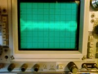
i finally took some picture of the output waves.
I am just thinking how i am gonna see a 5uV output signal.
Even if my scope would be nice and perfectly working, the highest input sensitivity would be 5mV/div.
Anyways i' m currently using a X10 probe.
The Volt/div knob is set up to the maximum sensitivity (5mV/div).
Without input signal (input shorted) i have the output shown on the picture.
Time/div is set up to its maximum frequency (0.01us/div).
I se two main frequency:
The highest frequency seems to be one division and therefore 100MHz... ...pretty high...uhm?
Could this freq damage an amp or a tweeter?
I also see a lower frequency that seems to be a 10MHz.
I don't see any other harmonic.
I don't know if i could safely hook this preamplifier to the rest of the chain without damaging tweeter or output transistors.
(the analysis and picture continue on the next post)
Attachments
- Status
- This old topic is closed. If you want to reopen this topic, contact a moderator using the "Report Post" button.
- Home
- Amplifiers
- Pass Labs
- preamplifier Pass X2.0/1