The one I attached will do nicely - it sounds very good and it's easy to build. F5 is very light load (100k).
R6/R1 ratio sets the gain (make them both 1k for the gain of 2V/V or 6 dB) and P1 sets the DC offset on output.
You can use F5's PS to make a regulated PS for this preamp.
Input pair of K170/J74 can be GR or BL ; output ones are BL or V.
Hi JUMA , I can drive with your preamp a F5 TURBO v2 ?, the input voltage is 33 volts, while F5 is 25v. Thanks
Regards
Hi JUMA , I can drive with your preamp a F5 TURBO v2 ?, the input voltage is 33 volts, while F5 is 25v. Thanks
Regards
Yes, you can use it for F5Tv2
I think you mean the PS rail voltage is 25/33V, not the input voltage.
Audio san,
yes, I suppose you are right. I am so bad at guessing the other people's thoughts.
Who wants the clear answer should ask the clear question...
Anyway, if we are talking about the preamp with 7x12 regulators (that's also unclear, it's obviously such a hard job to put the number of the post with the schematic in the question) they will handle 33V at the input.
Thanks for the answers and excuse my English.
I wanted to say that I will use the F5 turbo rail psu that has 33V. The F5 has 24V and there is a difference of 9 V. I have read in the specifications of the 78L12 that the input voltage can be up to 40V, but I wondered if you need to put some resistance at the input to the preamplifier.
Thanks again for the answers.
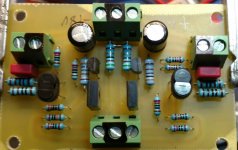
After few months of experimenting here is the circuit that sounds best to me - it's the same topology as the first one in this thread but with BJTs in output and higher Id through JFETs (6ma).
It takes the +/- 24V from F5 (they are both in the same case - F5 as integrated amp) and preamp's OUT is connected directly to F5's input.
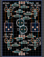
I used the PCB from the post #3 of this thread but with some diferent components and values.
And another thread resurrected...
What is the output impedance of this circuit? Could it drive the 600Ohm transformer winding of an M2 directly?

More than 100 Ohms.What is the output impedance of this circuit?
With some losses yes, but I would go for 50 Ohms or less.Could it drive the 600Ohm transformer winding of an M2 directly?
More than 100 Ohms.
With some losses yes, but I would go for 50 Ohms or less.
Hm, OK thx. Is there a meaningful way to teach this circuit to do 50 or less?
Yes, increase the OLG and the feedback loop will do the rest.Hm, OK thx. Is there a meaningful way to teach this circuit to do 50 or less?
Or add the EF stage or some buffer at the output.
Edit: I see now that I made a typo in the post #467 (first sentence) - it's more like 1000 Ohms (1k).
Last edited:
JFET-CCS-BOSOZ
Years old thread.... But has as a snappy title!.. search friendly.
Want to thank Juma for all the schematic's and information, simple circuits with good explanations.
I was looking around today because I need some gain, mostly use computers for source and many amps just don't put out much with a .5vac signal, its not enough. found this and made it.
Looked at many others but settled on this one to try out. Its going infront of a Pre with Jfet inputs.
My 2SK170 are 9.2 IDSS, so changed 33R CCS resistors to 51R to lower current, its now 6.4ma each with +-18V supply's so 70% ..... thinking of going to 43R to get that a bit higher
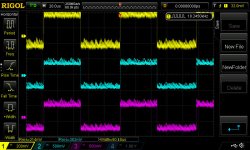
Sig gen has a bit of noise, need new cable for it. But the wave is nice and sharp. used a 39K load resistor.


Years old thread.... But has as a snappy title!.. search friendly.
Want to thank Juma for all the schematic's and information, simple circuits with good explanations.
I was looking around today because I need some gain, mostly use computers for source and many amps just don't put out much with a .5vac signal, its not enough. found this and made it.
Looked at many others but settled on this one to try out. Its going infront of a Pre with Jfet inputs.
My 2SK170 are 9.2 IDSS, so changed 33R CCS resistors to 51R to lower current, its now 6.4ma each with +-18V supply's so 70% ..... thinking of going to 43R to get that a bit higher
Sig gen has a bit of noise, need new cable for it. But the wave is nice and sharp. used a 39K load resistor.


Attachments
Last edited:
J310 version
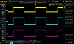
Today I tried J310's, with IDSS of 38ma, it looks much better, at least to me.
there is no way to run these at 80% of IDSS without heatsinks on the CCS and jfets.
tried 24ma but was hot, finger three second Hot....
so put it back at 14ma with R5 of 33R,
did change tale resistors to 50R - 50R
load is 39k and gain is3x
this might work very well
Attachments
Last edited:
Q1 & Q1 should operate @ roughly 30% to 90% of their Idss.
If you have 10mA jFETs then R5 should pass between 6mA and 18mA.
Once you have decided what Id you want to operate at you then select R3 and R8 to drop ~8volts across each.
Pq of jFETs = Id * Vds and for 90% @ 10mA Idss you end up with Pq=9mA*10V=90mW << 200mW
You definitely do not want 24mA passing through your jFETs.
Thank You that makes sense... was able to adjust ratios and its better now.
14ma is 36% of IDSS and 126mw dissipation @ 9v Drain to source
I wanted to try the J310 cause they are cheap.. and save my few K170's
AND Mostly Because:
Zen Mod said: will work there ...... as a charm
working on Juma's All BJT version now
14ma is 36% of IDSS and 126mw dissipation @ 9v Drain to source
I wanted to try the J310 cause they are cheap.. and save my few K170's
AND Mostly Because:
Zen Mod said: will work there ...... as a charm
working on Juma's All BJT version now
Last edited:
After few months of experimenting here is the circuit that sounds best to me - it's the same topology as the first one in this thread but with BJTs in output and higher Id through JFETs (6ma).
It takes the +/- 24V from F5 (they are both in the same case - F5 as integrated amp) and preamp's OUT is connected directly to F5's input.
I used the PCB from the post #3 of this thread but with some diferent components and values.
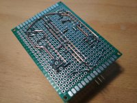
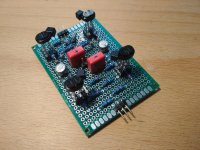
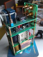
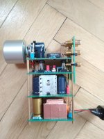
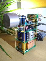
I built a Juma preamplifier(-tower
") .
.Schematic: post #53
The parts came from my drawers, the size of the Chinese proto boards are 5×7cm.
On the lower stage is the mains transformer, rectifier brideges, and RC filters. The next one is a power reg with LM317/337.
Above is the Juma's pre. I used the CircuitMaker to optimizing the traces. You can see the project here, if you are registered in.
On the top is the input selector, two inputs with reed relays, 20k Alps pot. The backboard is the same size, I drilled the holes for the rca's and for cable zip for fixing it on the tower. The standoffs are M2 sizes from Banggood, but you can buy those cheaper on Aliexpress.
Thanks Juma!
Attachments
Last edited:
- Status
- This old topic is closed. If you want to reopen this topic, contact a moderator using the "Report Post" button.
- Home
- Amplifiers
- Pass Labs
- Preamp ideas for F5