It is not impossible to achieve gain 40 dB (100x), in this case you need to decrease value of resistor between emitters of input pair to some 20 Ohms. But distortion will get into percents, i.e. 100x higher than original circuit.
I would recommend no more gain than 30 dB (30x approx.), this is for resistor 200 Ohms between emitters of input pair. You will have to play DC game again.
I would recommend no more gain than 30 dB (30x approx.), this is for resistor 200 Ohms between emitters of input pair. You will have to play DC game again.
I see.
How about making 2 "preamp concept" in series, each have gain of 10 (that makes total =100X), will this have the same "percent" distortion?
If it is the same, it is better to make 1 with 100X gain, due to simplicity.
This is difficult for me to decide, since the whole thing is non-feedback, distortion raise is confusing
Hi, PMA,
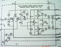
This is the McIntosh schematic that makes me think about transistor based ccs. The final's voltage is +/-35V.
If you notice in the attachment, something is strange. The output rail is only +/-35V, but McIntosh loaded the differential with 47k to +105V and load the VAS with 3k6 to +100V.
It is certainly more difficult and more costly to make additional 105V, just to drive 2 nodes with small mA requirement, compared to making transistor based ccs that can work from 35V.
If it is not important reason, I'm sure they won't do it. But they do it the hard way.
In your opinion, why McIntosh do it the hard+expensive way?
Attachments
Hi Uwe,
there is nothing especially new, after listening presentation in our hifi community the preamp has been quite successful here in CZ, 14 assembled boards were sold after 1st announcement, and very well rated. For that reason, I will not publish the PCB files.
Best regards,
Pavel
there is nothing especially new, after listening presentation in our hifi community the preamp has been quite successful here in CZ, 14 assembled boards were sold after 1st announcement, and very well rated. For that reason, I will not publish the PCB files.
Best regards,
Pavel
Hi Uwe,
http://web.telecom.cz/macura/dispre.jpg - is more than enoughCan you publish the PCB on you Website ?
Greg Erskine said:Hi Pavel,
I have a very technical question: "Why did you use one Philips head bolt that doesn't match the others?"
BTW, I prefer Allen head.
regards
Hi Greg,
just took something available from my component shelf
I made PCB for DisPre, today. I can post only top view. Need to ask Pavel for the rest .
ps: Greg, how are You?
Boban
.An externally hosted image should be here but it was not working when we last tested it.
ps: Greg, how are You?
Boban
...
There are some problems with file hosting server. Here we go again:
Boban
There are some problems with file hosting server. Here we go again:
An externally hosted image should be here but it was not working when we last tested it.
Boban

 .
.
- Status
- This old topic is closed. If you want to reopen this topic, contact a moderator using the "Report Post" button.
- Home
- Amplifiers
- Solid State
- Preamp concept