noname said:
100 mV input 400 mV output for the spectrum presented.
Is it a maximum signal level you plan to use?
I will certainly increase supply voltage from +/-12V to +/-18V at least, this will reduce distortion. Further, the circuit will be optimized.
Depending on the power amp, the maximum (peak) signal level that I can use is 1.0 Vp, i.e. 0.707 Vrms.
Well - I have assembled the preamp and started listening tests. I am very impressed by its open, dynamic and emphatic sound. Also soundstage is excellent. I will return with some photos and more comments in several days.
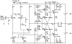
The PCB has groundplane on most of upper layer surface. The amp is extraordinary fast, but due to its non-global feedback topology it makes no problem.
The PCB has groundplane on most of upper layer surface. The amp is extraordinary fast, but due to its non-global feedback topology it makes no problem.
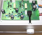
PMA said:Well - here is the result.
I can only say, WOW !
lumanauw said:
Do you always make prototype as neat as that? The PCB is high quality. My prototype(s) are a mess.
Yes, I mostly make them this way. This is a high speed circuit and needs proper PCB. To achieve hum/EMI supression and proper function, I have to do it this way. Breadboards do not give good results, and I am interested to know what are the circuit's real parameters.
build my first Circuit
Hello !
Today i build a first version of PMAs Preamp concept.
I connect a Behringer UB802 at the Diamond Buffer Driver and drive a 8Ohm Speaker.
One Channel of the IB802 is connectet by an C=3µ3 and R=10kOhm Network in serial.
Power suppley is now +22,5V # 0V # -22,5V.
It sound good.
The new project page
Attachments
Hi, PMA,
How much clean voltage out +/-Vpp that comes out from +/-15V supply?
I wanted to combine this with another of your design, NP-PMA.
NP-PMA will be running open-loop (because it is good for this), and get the full voltage swing from this very design of yours.
If the rail of output stage (NP-PMA) is +/-45V, how much voltage do I have to make with this preamp (for gaining full voltage swing that gives perfect output to +/-45Vpp)?
If it is used for this purpose, do you have suggestion what to change (due to higher voltage rail, and it is used for power amp front end, instead of preamp like the original design of yours)?
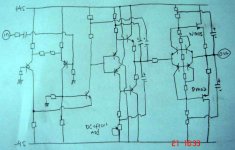
This is what I have in mind. Both are your desings, but I remove CCS transistor(s) to get minimum transistor in the whole amp. Replacing them with bootstrapp. It is openloop power amp.
What do you think? How much % voltage will I loose compared to +/-45V voltage rail?
What do you think? How much % voltage will I loose compared to +/-45V voltage rail?
Attachments
Hi David,
I created a webpage in english
http://web.telecom.cz/macura/dispre_en.html
please visit it to find some answers. Output voltage swing for +/-15V is +/-12V.
Cheers,
Pavel
P.S. The distortion would get higher for such output voltage. In case you are interested, I can make measurements for large output swing sometimes later. Measurements on my website are related to 0 dB = 1Vrms
Thanks PMA,
I can only read English, cannot read your original website
What should be changed to make it a front end for poweramp?
I can only read English, cannot read your original website
P.S. The distortion would get higher for such output voltage. In case you are interested, I can make measurements for large output swing sometimes later. Measurements on my website are related to 0 dB = 1Vrms
What should be changed to make it a front end for poweramp?
Nothing - it drives very difficult loads without problems. Just consider the output cap, if you leave it, should be at least 47uF to drive "NP-PMA".
Good suggestion
If I put 47uF before NP-PMA, I must put a resistor to ground after 47uF. 22k is good enough to hold NP-PMA at 0 DC offset?I think I read your explenation on how to adjust the DC offset of this preamp. But I search for it, it is gone now. Where is the explenation for adjusting DC offset of this preamp?
lumanauw said:Hi, PMA,
Have you looked at the drawing on post #52?
Not yet, I have working time now, so I can respond only briefly. Will try in the evening.
David,
Actually the DC is set by R21 resistor in schematic I posted here:
http://www.diyaudio.com/forums/showthread.php?postid=748405#post748405
I reviewed your post No. 52. Usually I am a little bit reserved to assess circuits that I have not simulated or better built. Did you have any special reason to substitute CCS by bootstraps? In case you dramatically change supply voltages, you will have to change component values as well. I am concerned about DC stability of your circuit.
Cheers,
Pavel
- Status
- This old topic is closed. If you want to reopen this topic, contact a moderator using the "Report Post" button.
- Home
- Amplifiers
- Solid State
- Preamp concept